© National Instruments | 1-11
M Series User Manual
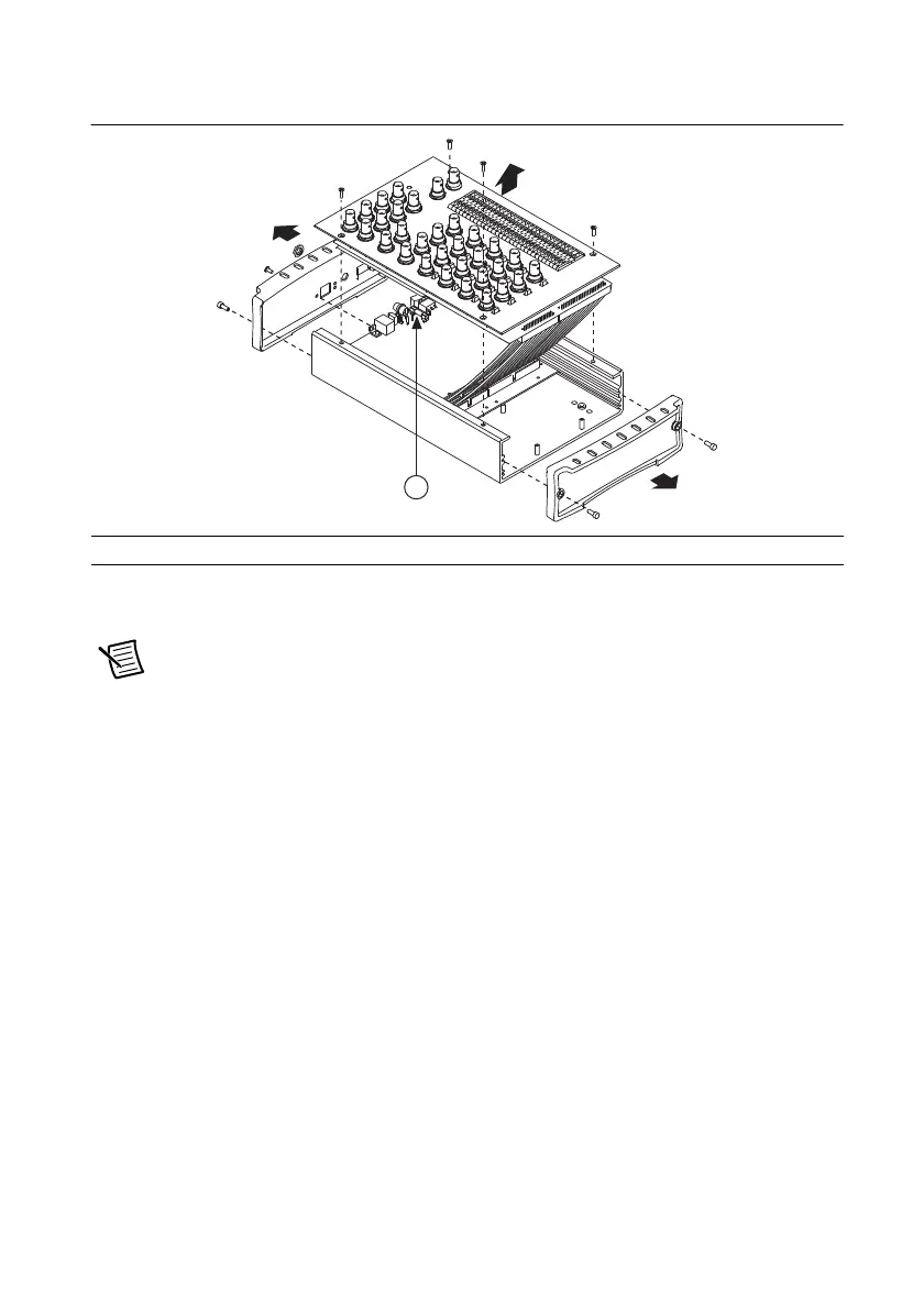
Figure 1-9. USB-62xx BNC Fuse Location
3. Remove both end pieces by unscrewing the four sockethead cap screws with a 7/64 in. hex
wrench.
Note The end pieces are attached using self-threading screws. Repeated screwing
and unscrewing of self-threading screws will produce a compromised connection.
4. With a Phillips #2 screwdriver, remove the Phillips 4-40 screw adjacent to the USB
connector.
5. Remove the nut from the power connector.
6. Remove the four Phillips 4-40 screws that attach the top panel to the enclosure and remove
the panel and connector unit.
7. Replace the broken fuse while referring to Figure 1-9 for the fuse location.
8. Replace the top panel, screws, nut, and end pieces.
1 T 2A 250V (5 × 20 mm) Fuse

 Loading...


