26 | Wiring the radar system
4.4 Radar processor 2 kW: Connect the interconnection cable to
the radar processor
If the Interconnection cable is not attached or needs to be changed use the following steps
Run the 2 kW interconnection cable (either the standard 15 m [49 ft] or the optional 20 m [65.5
ft] cable) from the scanner to the radar processor.
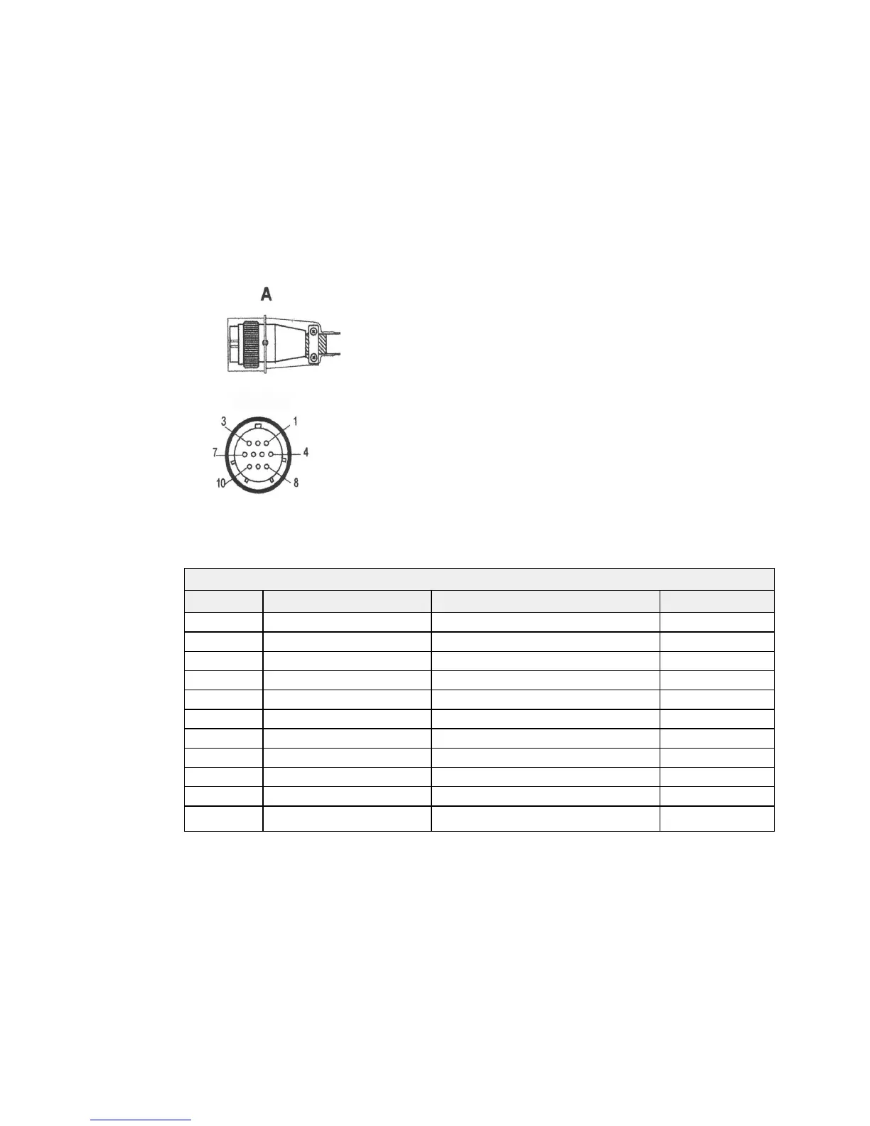
Push the round connector (A) of the 2 kW interconnection cable into the scanner connection on
the radar processor and tighten the locking nut.
The interconnection cable pin details are provided here for information, in case the connector
needs to be removed to feed the cable.
The front view of the 2 kW interconnection cable is shown above.
2 kW interconnection cable pin details
Pin Color/Name Signal name AWG size
1 Green (thick) Power #12
2 Yellow (thick) Power GND #12
3 Green (thin) Pulse width #24
4 Clear coax signal Video #24
5 Drain wire for 4 Video GND #24
6 Drain wire for 7 Trig GND #24
7 Black coax signal Trig/STC #24
8 White BZ Tune to scanner #24
9 Yellow Tune from scanner #24
10 White (thick) No connection #12
Shell Braid shield
 Loading...