Wiring the radar system | 27
4.5 Radar processor 4 kW: Connect the interconnection cable to
the radar processor
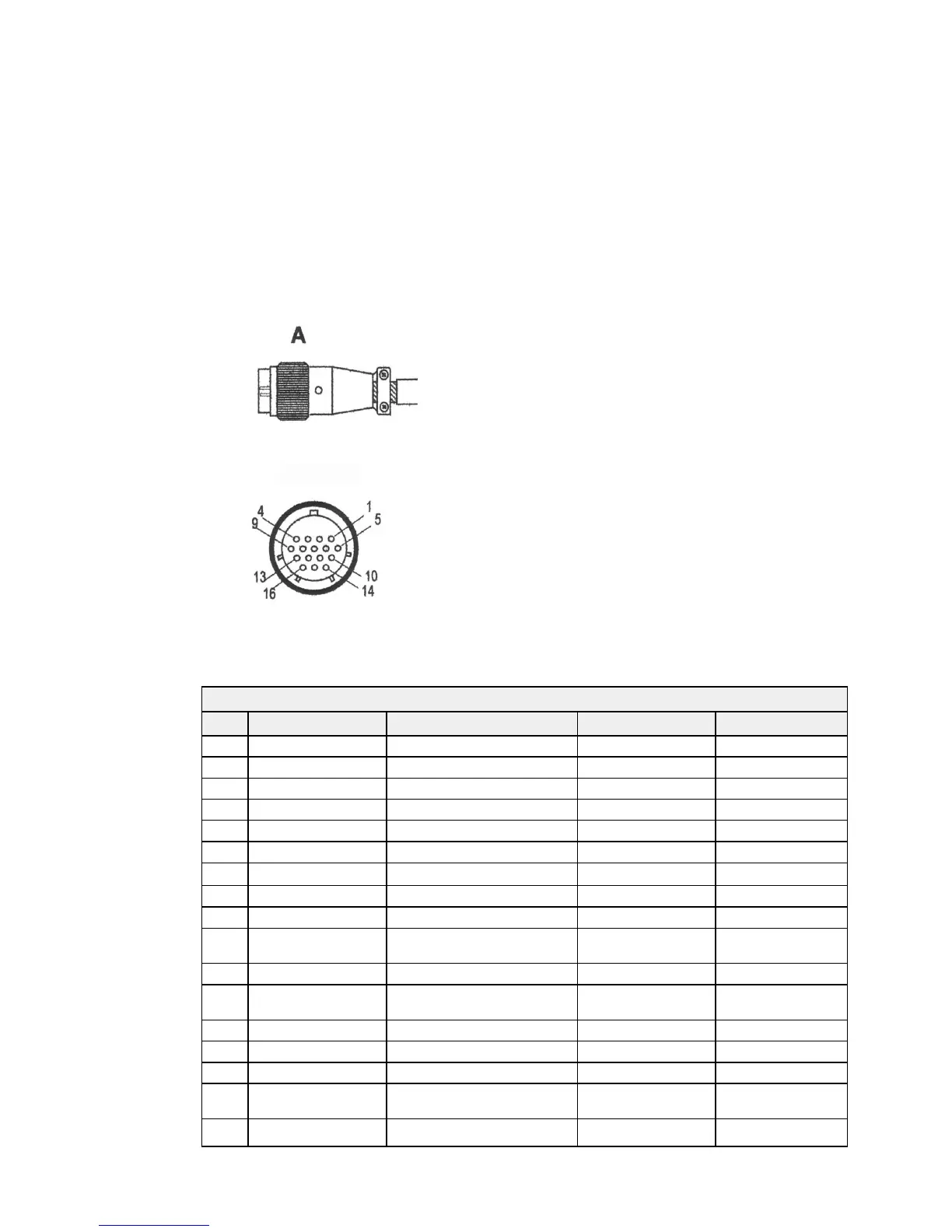
• Run the 4 kW interconnection cable from the scanner to the radar processor.
• Push the round connector (A) of the 4 kW interconnection cable into the scanner
connection on the radar processor and tighten the locking nut.
• The interconnection cable pin details are provided here for information, in case the
connector needs to be removed to feed the cable.
The front view of the 4 kW interconnection cable is shown above.
4 kW interconnection cable pin details
Pin Signal Name Description/Remarks Color/Name AWG size
1 2 A Input DC power Isolated Ground Blue (thick) #16
2 2 A Input DC power Isolated Ground Purple (thick) #16
3 1 A Input DC power Isolated DC 10.8 V to 42 V Red (thick) #16
4 1 A Input DC power Isolated DC 10.8 V to 42 V Yellow (thick) #16
5 VDE Video Return Coax return Drain wire (Coax line) #24
6 No connection Not used No connection
7 No connection Not used No connection
8 No connection Not used No connection
9 COM(+) COM PORT RS485 Yellow (thin) #24 twist pair
10 VD Video Output Coax cable
@-2 V=100 dB
Clear Coax line #24
11 No connection Not used No connection
12 BZ Bearing Zero BZ - HDG Flash -
open collector
Green (thin) #24
13 COM(-) COM PORT RS485 White (thin) #24 twist pair
14 TIE Trigger Return Shield return Drain wire #24
15 TI Trigger Shield cable @ 1/PRF Shield line #24
16 BP Bearing Pulse 2048
pulses/rotation
Orange (medium) #18
Shell
Braid shield
 Loading...