48 Setting the DIP Switches
CAUTION
Do not remove the front cover unless the power to the
boiler is turned off or disconnected. Failure to do so may
result in electric shock.
The boiler has 2 sets of DIP switches on the main circuit board
(PCB) and 2 sets of DIP switches on the front panel. DIP switches
are used to control the functionality of the boiler. Set the DIP
switches appropriately, based on the installation environment.
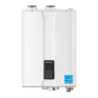
6.1 PCB DIP Switches
DIP Switch 1 (6 switch unit)
The DIP SW 1 on the circuit board configures the operation status
and model/capacity settings.
1 2 3 4 5 6
ON
1 2 3 4 5 6 7 8
ON
Switch Function Setting
1 & 2
Operation
Status
Normal Operation 1-OFF, 2-OFF
2-stage MAX 1-ON, 2-OFF
1-stage MIN 1-OFF, 2-ON
1-stage MAX 1-ON, 2-ON
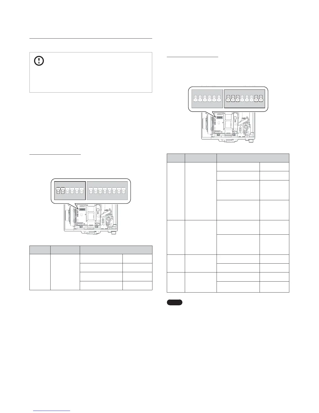
Dip Switch 2 (8 switch unit)
The DIP SW 2 on the circuit board configures the temperature
control modes, country, and enables or disables the space heating
thermostat.
1 2 3 4 5 6
ON
1 2 3 4 5 6 7 8
ON
Switch Function Setting
1 & 2
Space Heating
Temperature
Control
Supply Temperature 1-OFF, 2-OFF
Return Temperature 1-ON, 2-OFF
System Supply
Temperature (with
optional sensor)
1-OFF, 2-ON
System Return
Temperature (with
optional sensor)
1-ON, 2-ON
3
DHW Tank
Temperature
Control
DHW Supply
Temperature
3-OFF
DHW System Supply
Temperature (with
optional sensor)
3-ON
7
Space Heating
Thermostat
Used 7-OFF
Unused 7-ON
8
Exhaust
Temperature
Control
Used 8-OFF
Unused 8-ON
Note
When PCB DIP switch 2 #8 is set to On, ensure that
CPVC piping is used for exhaust venting.
6. Setting the DIP Switches
 Loading...