TRANSIT ENTRY | INSTALLATION GUIDE
Connections
9/30
3.2 WIRE CONNECTIONS
Wire connections to the TRANSIT Entry are user friendly spring cage terminal
connectors.
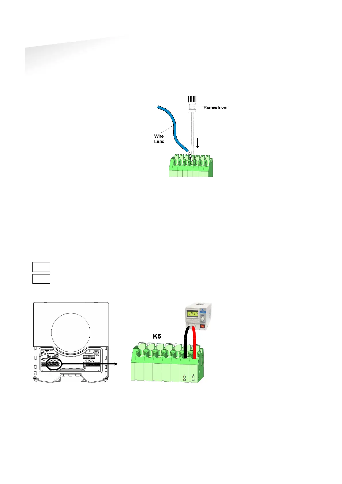
Connection procedure with spring cage terminal connectors.
1 Strip wire lead for about 9 mm (0.35
inch).
2 Push the screwdriver straight down to
release the spring cage. Use a slotted,
narrow-head screwdriver.
3 Insert the wire lead into the wire
terminal.
4 Remove the screwdriver, this clamps
the wire.
5 Gently pull on the installed wire to
make sure the connection is reliable.
Figure 8: Wiring detail
See appendix
Error! Reference source not found.
A for recommended maximum and
minimum conductor cross sections and for the recommended wire stripping length.
3.3 POWER SUPPLY
The TRANSIT Entry requires DC power supply in the range from 12 – 24V. Maximum
current consumption is 1A @ 12VDC, 0.5A @ 24VDC.
Connections
DC-
Power supply 0V.
DC+ Power supply 12 - 24VDC.
Figure 9: Power supply wiring
Each connector terminal
can accommodate only 1
solid or stranded wire.
Wiring is normally done
without ferrule
s. However,
it is possible to use ferrules,
provided that they are
properly crimped.
The power supply
connection has an auto
resetting fuse protection.

 Loading...