GEO M12 HARDWARE SETUP PROCEDURE Page 27/90
6.2 General Description
6.2.1 GEO M1210 and GEO M1220
IMPORTANT
GEO M1210 & GEO M1220 share the same geometry and fittings, but different wavefront
curvatures. In order to distinguish one from the other,
GEO M1210 is marked with the following sign on its sides:
GEO M1220 is marked with the following sign on its sides:
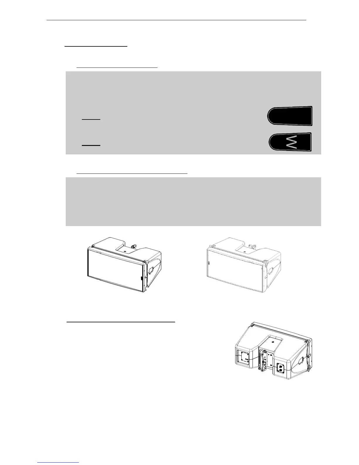
6.2.2 GEO M12 “Left” and “Right” configuration
GEO M12 can be installed “Left” or “Right”:
- “Left” means HF waveguide is left as seen from front
- “Right” means HF waveguide is right as seen from front
GEO M12 can be connected to bumpers “Left” or “Right” by simply flipping the cabinets.
Whenever possible, NEXO recommends symmetrical designs (preferably HF waveguide
inwards in stereo configurations)
GEO M12 “Left” GEO M12 “Right”
6.2.3 GEO M12 and MSUB18 rigging systems
GEO M12 features a 3-points rigging system, 2 for front
connection, and 1 for rear connection and angle splay settings.
- Front connection of two subsequent modules is ensured by
an AutoRig
TM
system, with 3 positions: open / ready to lock /
locked (only on touring version).
 Loading...