Page 8/90 GEO M12 GENERAL SET-UP INSTRUCTIONS
2 GEO M12 GENERAL SET-UP INSTRUCTIONS
2.1 GEO M12 and MSUB18 connections
GEO M12 and MSUB18 are connected with Speakon NL4FC plugs (not supplied). A wiring diagram is
printed on the connection panel located on the back of each cabinet. The 4 pins of the Speakon sockets
identified in / out are connected in parallel within the enclosure.
Either connector can be used to connect amplifier or to link to an additional GEO M12 cabinet or to link
to an optional MSUB18 (if present). Therefore, a single 4-conductor cable can connect two amplifier
channels to various GEO M12s and/or MSUB18 subwoofers.
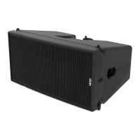
2.1.1 GEO M12 connectors
Selection of Active or Passive Mode
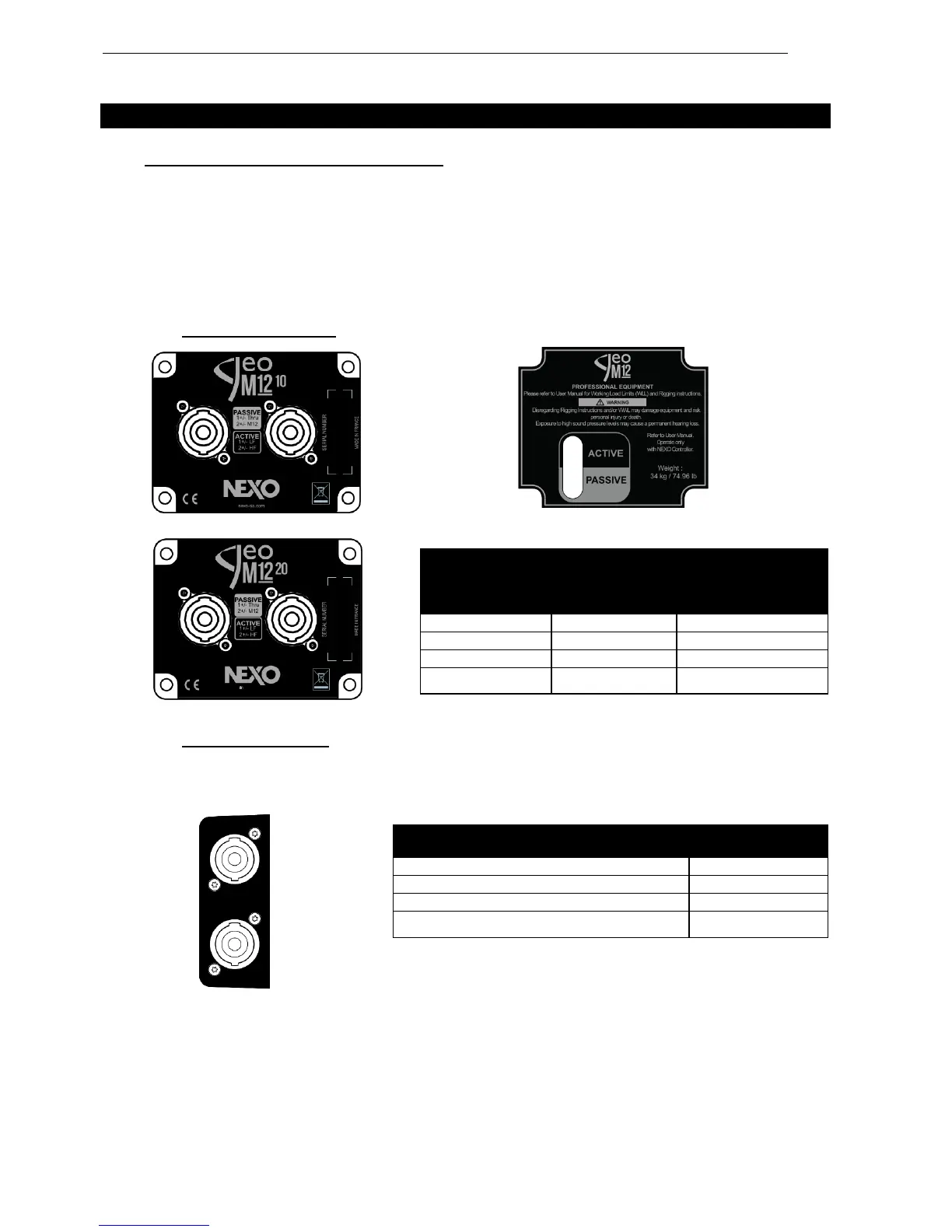
2.1.2 MSUB18 connectors
MSUB18 features 2 connector panels with 2 Speakon NL4 each so that cabling is always done at the
back independently of cabinet being set frontwards or rearwards for cardioid configurations.
 Loading...