Page 66/90 SYSTEM CHECK ALIGNMENT GUIDELINES
7 SYSTEM CHECK ALIGNMENT GUIDELINES
The NEXO TD Controllers factory delay presets are optimised to provide the best possible crossover
between the GEO M12 and MSUB18 systems. The reference point for this adjustment is the front of each
cabinet. (This means that the internal delays needed to achieve a correct time alignment are set for
cabinets standing next to each other with both fronts aligned). We recommend that the system is adjusted
so that arrivals from GEO M12 and MSUB18 are coincident at a fairly distant listening position.
7.1 GEO M12 Vertical Cluster design
Cluster design must be done with NS-1, which provides very intuitive and fast method to determine all
cluster geometry parameters in relation to venue where cluster is implemented.
NS-1 is a freeware available for all Nexo users at nexo-sa.com
IMPORTANT
Never install a GEO M12 and/or MSUB18 cluster without checking its acoustical
performances and mechanical safety in NS-1 prior to installation.
Please contact your local distributor for assistance and/or training NS-1
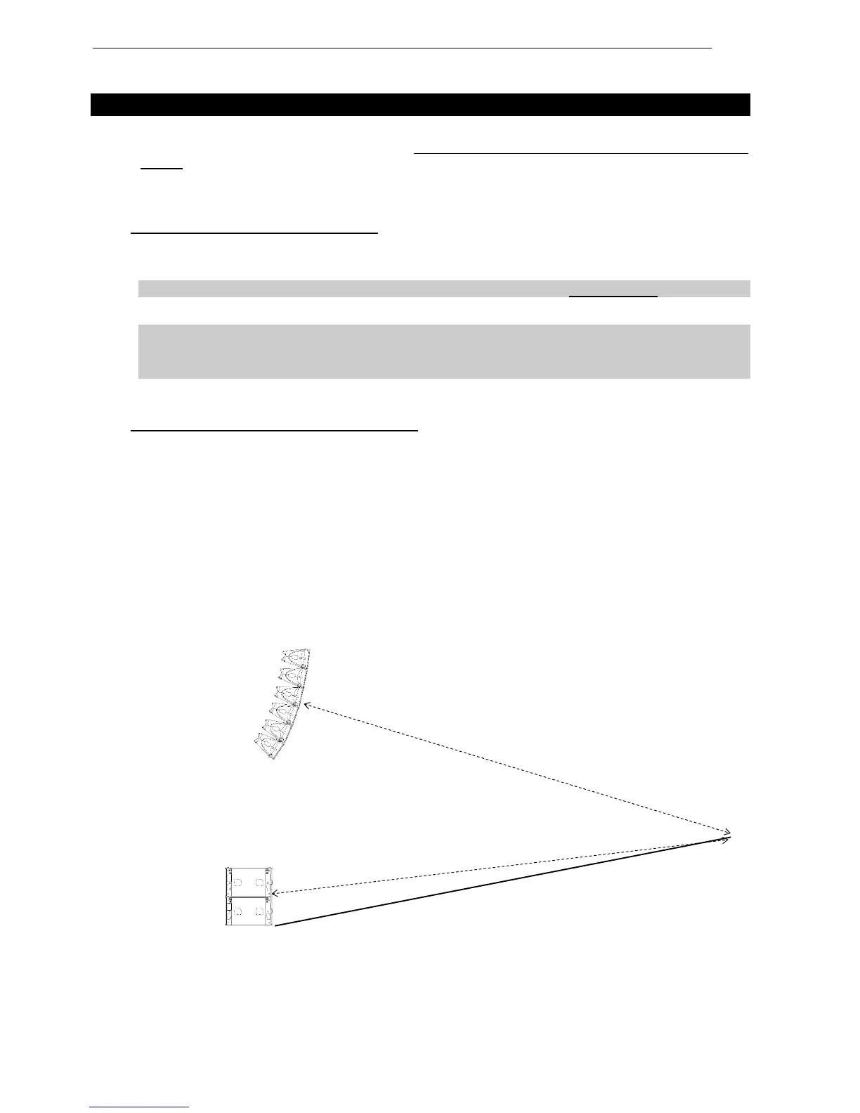
7.2 Stacked MSUB18 and Flown GEO M12
In the example below, r
1
being the distance from GEO M12 array to listener position, and r
2
being the
distance from MSUB18 to listener position, the distance difference is then r
1
–r
2
(specified meters or feet).
r
1
> r
2
, the delay should be set on the MSUB18 NEXO TDcontroller channel.
r
1
< r
2
, the delay should be set on the GEO M12 NEXO TDcontroller channel
To convert the result in time delay (specified in seconds), apply:
t = (r
1
-r
2
)/C r
1
and r
2
in meters, C (sound speed) 343 m/S.
Set the units to meters, feet or seconds according to your preference). Delay will have to be adjusted
according to the distance difference r
1
–r
2
(see figure below).
 Loading...