1010
support.hysecurity.com
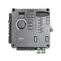
MERCURY 310 Controller
User Guide
EDGE SENSORS: One or more contact sensors (edge
sensors) shall be located at leading edge, trailing edge, and
post-mounted, both inside and outside of a sliding gate.
One or more contact sensors shall be located on the inside
and outside leading edge of a swing gate. Additionally, if the
bottom edge of a swing gate is greater than 6"(152mm) but
less than 16"(406mm) above the ground at any point in its
arc of travel, one or more contact sensors shall be located
on the bottom edge.
SENSOR SECURITY:
A hard-wired contact sensor shall
be located and its wiring arranged so that communication
between sensor and gate is not subjected to mechanical
damage.
TYPE A ENTRAPMENT PROTECTION: In
Type A
entrapment protection, the controller monitors the electrical
resistance of the actuator motors, so if a moving gate comes
up against the physical resistance of an immovable object,
it will cause the gate to stop, hence limiting the force..
TYPE C ENTRAPMENT PROTECTION:
In Type C
entrapment protection, the controller monitors the actuator
encoder output, and if there is an unexpected decrease in
speed, it will cause the gate to stop, hence limiting the force.
SENSOR FUNCTION and COMMUNICATION:
A wireless
sensor that transmits its signal to gate operator must be
located so its signal is not impeded by building structures
or other obstructions. All sensors must be installed so that
they function as intended for end-use conditions.
UL 325 LISTING:
Edge sensors and photo eyes must
be tested and labeled as “Recognized Components” or
otherwise certi ed to UL 325 requirements in order to
CAUTION
A contact or non-contact sensor is also required to
protect against possible entrapment if gate opens to a
position less than 16 inches from any object, such as
a post or wall.
be deemed acceptable for use in a gate operator. Study
Important Safety Instructions and consider your speci c
installation to determine where greatest entrapment
risks exist. Locate edge sensors and/or photo sensors
accordingly. Be certain that a su cient number of sensors
are used so that pedestrians are protected from entrapment
in both directions of gate travel and all hazard areas are
fully protected. Most HySecurity gate operators require
external entrapment sensors that utilize Normally Closed
(NC) contact means of monitoring. HySecurity gate
operators utilizing the SmartCNX Controller require external
entrapment sensors that have a 10k Ohm or 4-wire pulsed
monitoring scheme. Refer to UL website at www.ul.com
for
most up-to-date list of gate operator safety standards (UL
325). Mercury 310 controller can monitor 10k sensors as
well as BlueBus photo eyes.
RECOMMENDED EXTERNAL ENTRAPMENT PROTECTION SENSORS LIST
UL 325 Standard:
’ The operator shall monitor for the presence of every device at least once during each open and close cycle (32.1.8).
’ It shall not be possible to make simple modi cations in the eld by adding, suppressing or changing, either on the
operator or external entrapment protection device(s), to bypass, interfere with, or otherwise defeat the monitoring
function. (32.1.10).
’ Entrapment zones are now de ned for each gate type (4.23, 4.24, 4.29, 4.34).
Swing Gates: To enable fully automatic operation, all SWING gate operators will require a minimum of ONE monitored
external entrapment protection sensor to protect entrapment zones in either the open or close direction of travel. However,
an additional monitored sensor is required if there is a risk of entrapment in both directions of gate travel.
Preferred solution for swing gates: A photo eye for the close direction and/or a hard-wired wraparound edge sensor on
the leading edge of the gate, which protects for both directions of gate travel.
IMPORTANT!
Installers must assess each speci c site and install
sensors that protect all potential entrapment zones.
For more information visit Gate Safety at www.hysecurity.com/gatesafety or
see latest operator manuals at https://support.hysecurity.com/hc/en-us
 Loading...