5
EN
• CLOSE = input for devices which control only the closing movement. It is
possible to connect contacts of the “Normally Open” type to this input.
• AERIAL = connection input for the radio receiver aerial (the aerial is incorpo-
rated in LUCY B).
5
FINAL CHECKS AND START UP
The manufacturers recommend you position the gate at approximately half
travel before starting the checking and start up phase of the automation. This
will ensure the gate is free to move both during opening and closure.
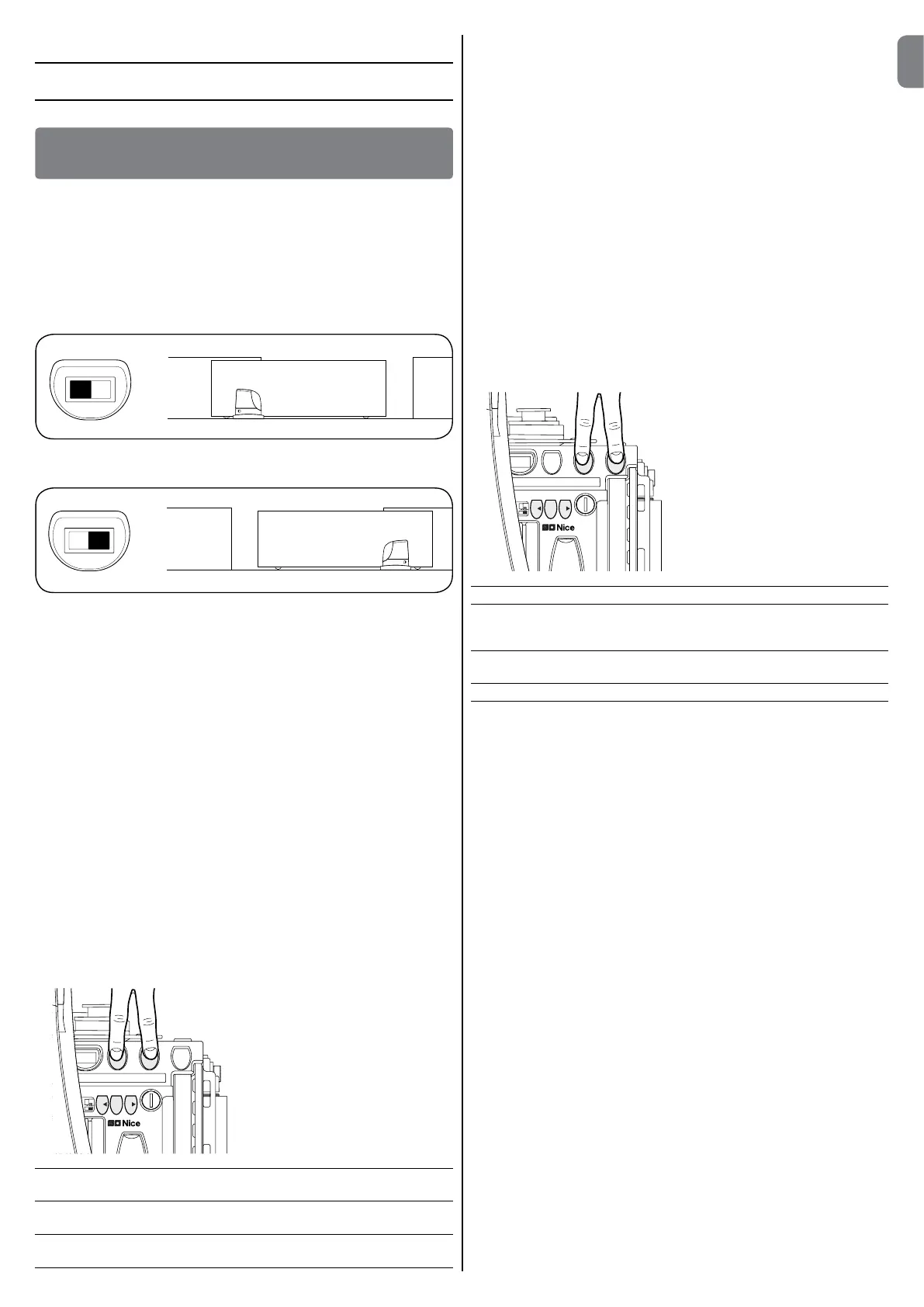
5.1-Selectingthedirection
The direction of the opening manoeuvre must be chosen depending on the
position of the gearmotor with respect to the gate. If the gate must move left
for opening, the selector must be moved towards left as shown in the Figure,
alternatively, if the gate has to move right during opening, the selector must be
moved towards the right as shown in the Figure.
5.2 - Connecting to the power supply
CAUTION!–Connecting RUN to the power supply must only be per-
formedbyqualifiedandexperiencedpersonnelinpossessionofthe
necessaryrequisitesandinfullrespectofthelaws,provisionsand
standardscurrentlyinforce.
As soon as RUN is powered up, you should check the following:
01. CheckthattheBlueBusledashesregularlyatthefrequencyofoneash
per second.
02. Makesurethattheledsonthephotocellsash(bothonTXandRX);the
typeofashingisnotimportantasitdependsonotherfactors.
03. MakesurethattheasherconnectedtotheFLASHoutputandtheindica-
tor light connected to the “Open Gate Indicator” output are off.
If the above conditions are not satisfied, you should immediately switch off the
power supply to the control unit and check the electrical connections more
carefully.
Please refer to the chapter on “Troubleshooting” for further information about
finding and analysing failures.
5.3 - Recognitionofthedevices
After connecting up the power supply, the control unit must be made to recog-
nise the devices connected up to the BLUEBUS and STOP inputs. Before this
phase, leds L1 and L2 will flash to indicate that recognition of the devices must
be carried out.
01. Press and hold keys [s] and [Set].
Stop
Set
Close
Open
L1 L2 L3 L4 L5 L6 L7 L8
02. Release the keys when leds L1 and L2 start to flash quickly (after around
3s).
03. Wait a few seconds until the control unit has completed the device recog-
nition procedure.
04. When the recognition stage is completed the STOP led must remain on,
while the L1 and L2 leds must go off (leds L3 and L4 may start flashing).
Devicerecognition,mode2
This configures:
• The BlueBus output with 12V auxiliary output; it may be used as a power
output for 12V electronic devices up to 6W;
CAUTION-ifyourunmode2devicerecognition,youcannolonger
use the BlueBus photocells.
• Using the OPEN and CLOSE terminals as photocell and photocell 2 safety
inputs respectively (for this function, refer to table 10 and fig. 18).
This mode is selected during device recognition, by holding down the [Open]
and [Stop] buttons for more than 8 seconds.
After 8 seconds, leds L1 and L2 start flashing very quickly; release the [Open]
and [Stop] buttons.
The connected devices recognition stage can be repeated at any time, even
after the installation (for example, if a device is installed); for performing the new
recognition see paragraph “8.1.6 Recognition of Other Devices”.
5.4 - Recognition of the length of the gate
Afterrecognizingthedevices,L3andL4ledsstartflashing;thecontrolunit
mustrecognizethelengthofthegate.Duringthisstage,thelengthofthe
gate is measured from the closing limit switch to the opening limit switch. This
measurement is required to calculate the deceleration points and the partial
opening point.
01. Press and hold the [Set] and [t]
keys
Stop
Set
Open
Close
L1 L2 L3 L4 L5 L6 L7
02. Release the keys when the manoeuvre starts (after approx. 3 s).
03. Check the manoeuvre in progress is an opening manoeuvre. If it is not,
press the [Stop] key and carefully check paragraph “5.1 Selecting the
direction”; then repeat the process from point 1.
04. Wait for the control unit to fully open the gate by reaching the opening limit
switch; the closing manoeuvre will start immediately afterwards.
05. Wait for the control unit to fully close the gate.
Gatelengthrecognition,mode2
This configures:
• Deceleration at the 10 cm position in opening and closing;
• 100% motor speed setup for opening and closing (extremely fast mode, see
table 8).
This mode is enabled during device recognition by holding down the [Stop]
and [Close] keys for more than 8 seconds. Leds L3 and L4 now start flash-
ing very quickly, at which point you can release the [Stop] and [Close] keys.
If the above conditions are not satisfied, you should immediately switch off the
power supply to the control unit and check the electrical connections more
carefully. Other useful information can be found in the chapter on “Trouble-
shooting”.
5.5 - Checking gate movements
On completion of the recognition of the length of the gate, it is advisable to
carry out a number of manoeuvres in order to check the gate travels properly.
01. Press the [Open] key to open the gate. Check that gate opening occurs
correctly, without any variations in speed. The gate must only slow down
when it is between 70 and 50 cm from the opening limit switch, and stop,
as a result of the limit switch, at 2-3 cm from the mechanical opening stop.
02. Press the [Close] key to close the gate. Check that gate opening occurs
correctly, without any variations in speed. The gate must only slow down
when it is between 70 and 50 cm from the closing limit switch, and stop, as
a result of the limit switch, at 2-3 cm from the mechanical closing stop.
03. During the manoeuvre, check that the flasher flashes at a speed of 0.5
seconds on and 0.5 seconds off. If present, also check the flashes of the
light connected to the S.C.A. terminal: slow flashes during opening, quick
flashes during closing.
04. Open and close the gate several times to make sure that there are no
points of excessive friction and that there are no defects in the assembly or
adjustments.
05. Check that the fastening of the RUN gearmotor, the rack and the limit
switch brackets are solid, stable and suitably resistant, also when the gate
accelerates or decelerates sharply.

 Loading...