11
EN
memorizedinthereceiver.
For more information refer to the instruction manual and the “Opera system
book” manual.
8.1.9 - Connectingandinstallingthebackupbattery
CAUTION!
– Electrical connection of the battery to the unit must be
performedexclusivelyaftercompletingallstagesininstallationand
programming, as the battery is an emergency power supply.
OnRUN400HSandRUN1200HS,youcaninstallbackupbatteriesviathe
PS524 charging interface, combined with the pair of batteries B12-B.4310
(12V - 7ah).
Proceed as shown in fig. 22:
01. Fit charging card PS524 as shown in step 1
02. Fit the batteries, already connected as shown in steps 2 and 3
03. Connect the battery connector to the PS524 (step 4) and then hookup the
connector cable to the control unit, as shown in step 5
04. Route the cable between the control unit and charging card as shown in
step 6.
Note - If necessary, the control unit and charging card may be removed by
depressing the tabs (fig. 23).
8.2 - Special functions
8.2.1 - “Always open” function
The “Always open” function is a control unit feature which enables the user
to control an opening manoeuvre when the “Step-by-Step” command lasts
longer than 2 seconds. This is useful for connecting a timer contact to the
“Step-by-Step” terminal in order to keep the gate open for a certain length of
time, for example. This feature is valid with any kind of “Step-by-Step” input
programming, except for “Close”. Please refer to the “Step-by-Step Function”
parameter in Table 8.
8.2.2 - “Move anyway” function
In the event that one of the safety devices is not functioning properly or is out of
use, it is still possible to command and move the gate in “Man present” mode.
Please refer to par. “Control with safety devices out of order” in the enclosure
“Instructions and Warnings for users of the RUN gearmotor” for further information.
8.2.3-Maintenancenotication
With RUN, the user is warned when the automation requires a maintenance con-
trol. The number of manoeuvres after the warning can be selected from 8 levels,
by means of the “Maintenance warning” adjustable parameter (see table 8).
Adjustment level 1 is “automatic” and takes into consideration the severity of
the manoeuvre, this being the force and duration of the manoeuvre, while the
other adjustments are established based on the number of manoeuvres.
The maintenance request signal is given by means of the flasher (Flash) or by
the light connected to the S.C.A. output when programmed as a “Maintenance
light” (see table 8).
The flasher “Flash” and the maintenance light give the signals indicated in table
14, based on the number of manoeuvres performed in respect to the limits that
have been programmed.
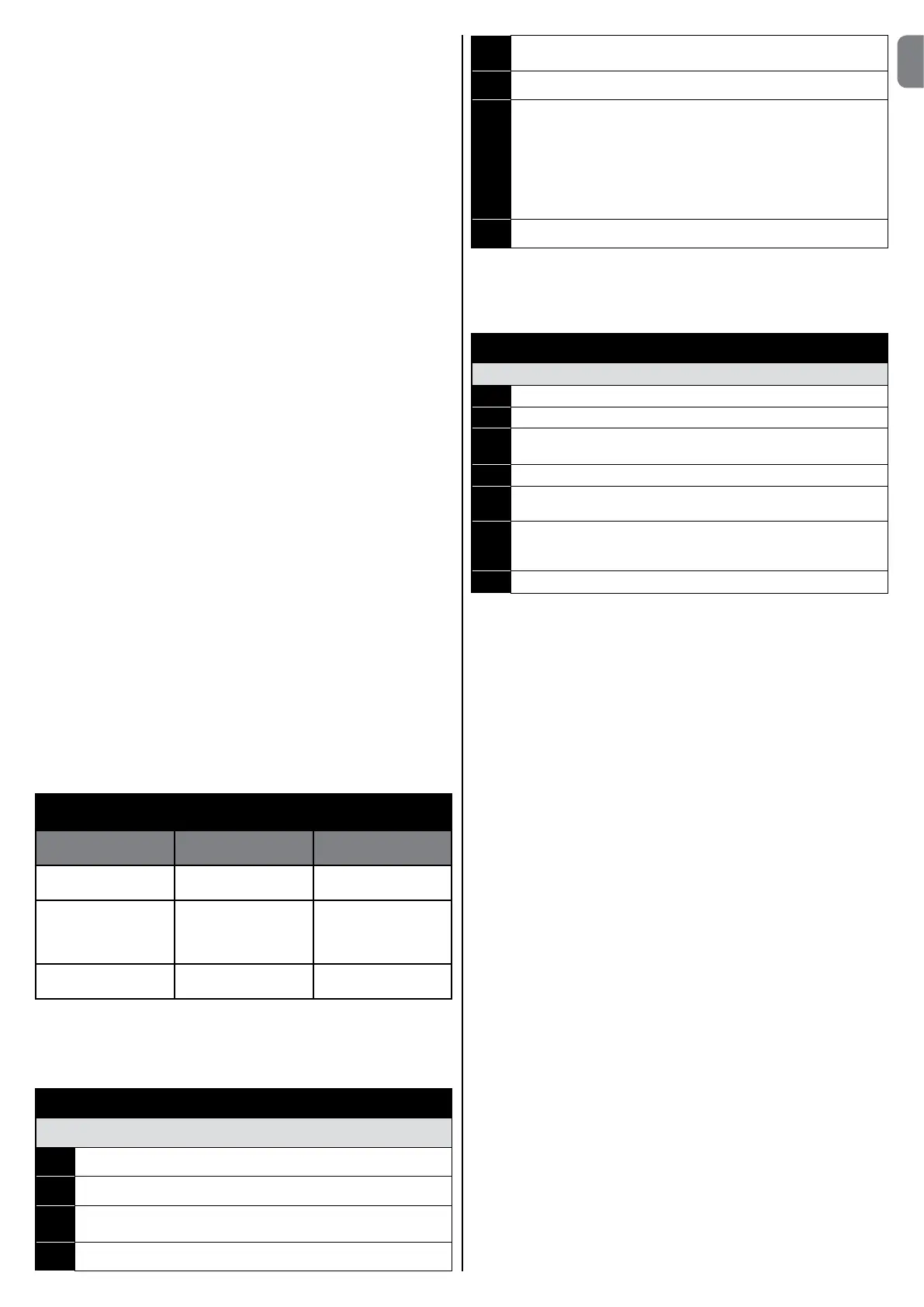
TABLE14-MaintenancewarningwithFlashandmainte-
nance light
Number of manoeu-
vres
Flash signal Maintenance light
signal
Lower than 80% of
the limit
Normal (0.5s on, 0.5s
off)
On for 2s when open-
ing begins
Between 81% and
100% of the limit
Remains on for 2s at
the beginning of the
manoeuvre then carries
on normally
Flashes throughout the
manoeuvre
Over 100% of the limit Remains ON for 2s at
the start and end of
the manoeuvre then
carries on normally
8.2.4-Controlofthenumberofmanoeuvresperformed
The number of manoeuvres performed as a percentage on the set limit can be
verified by means of the “Maintenance warning” function. Follow the indications
in Table 15 for this control.
TABLE 15
Checkofnumberofmanoeuvresperformed
01. Press and hold the “Set” key for about 3 seconds;
02. Release “Set” when led L1startsashing;
03.
Press “s” or “t”keytomovetheashingledontoL7,i.e.the“input
led”fortheparameter“Maintenancenotication”;
04. Press and hold down “Set” throughout steps 5, 6 and 7;
05. Wait approx. 3s after which the led associated with the current level of
theparameter“Maintenancenotication”willlightup.
06.
Press and release “s” and “t”;
07. Theledcorrespondingtotheselectedlevelashesafewtimes.The
numberofashesindicatesthepercentageofmanoeuvresperformed
(in multiples of 10%) with respect to the set limit.
For example: with the maintenance warning set on L6 being 10000,
10%isequalto1000manoeuvres;iftheledashes4times,this
means that 40% of the manoeuvres have been reached (being
between4000and4999manoeuvres).Theledwillnotashif10%of
themanoeuvreshasn’tbeenreached.
08. Release the “Set” key.
8.2.5 - Manoeuvre counter reset
After the maintenance of the system has been performed the manoeuvre coun-
ter must be reset. Follow the indications in Table 16 for this control.
TABLE 16
Manoeuvre counter reset
01. Press and hold the “Set” key for about 3 seconds;
02. Release “Set” when led L1startsashing;
03.
Press “s” or “t”keytomovetheashingledontoL7,i.e.the“input
led”fortheparameter“Maintenancenotication”;
04. Press and hold down “Set” throughout steps 5 and 6;
05. Wait approx. 3s after which the led associated with the current level of
theparameter“Maintenancenotication”willlightup.
06.
Press and hold keys “s” and “t” for at least 5 seconds, then release
them.Theledthatcorrespondstotheselectedlevelashesrapidly
indicating that the; manoeuvre counter has been reset;
07. Release the “Set” key.

 Loading...