2
EN
before resetting it.
• Theautomationmechanismcannotbeusedbeforeithasbeencommis-
sionedasspeciedinthechapteron“Testingandcommissioning”.
• Inspecttheautomationmechanismfrequentlytocheckforunbalancing,
signs of wear or damage to electrical cables and mechanical parts. Do not
use the automation mechanism if adjustment or repair is required.
• If it is not used for a long time, remove the optional battery and keep it in a dry
place to make sure it does not leak harmful substances.
• Thepackingmaterialsoftheproductmustbedisposedofincompliancewith
local regulations.
1.3 - Warnings about use
• Theproductisnotintendedforusebypersons,includingchildren,withlim-
ited physical, sensory or mental capacities, or who lack experience or knowl-
edge, unless supervised or trained in the use of the product by a person
responsible for their safety.
• Anychildrenneartheautomationsystemmustbekeptundersupervisionto
ensure that they do not play with it.
• Donotallowchildrentoplaywiththexedcontroldevices.Keepremote
control devices out of their reach as well.
• Cleanthesurfacesoftheproductwithasoft,slightlydampcloth.Useonly
water; do not use cleaning products or solvents.
2
PRODUCT DESCRIPTION AND INTENDED USE
This product is intended to be used to automate sliding gates used in residential
premises. CAUTION!–Allusesotherthantheintendedusedescribed
anduseinenvironmentalconditionsotherthanthosedescribedinthis
manualshouldbeconsideredimproperandforbidden!
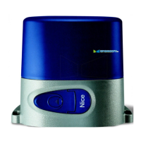
RUN is a line of one-way electromechanical gearmotors with electronic control-
ler and SM type connector for the wireless receiver (optional). Electrical con-
nectionswithexternaldevicesaresimpliedthankstouseofthe“BlueBus”,a
technique permitting connection of multiple devices with only 2 wires. The list
of devices compatible with RUN over the BlueBus network is given in Chap-
ter7.3.1“BlueBus”;anup-to-datelist,withcompatibilityspecications,isalso
available on www.niceforyou.com.
RUN has a remote programmer connector to facilitate installation, maintenance
and troubleshooting; see Chapter 7.8.1 “Remote programmer”.
Ifmainspowered,Runcanbettedwithabackupbatterytoprovidepower
during power failures so that it can be operated for several hours (see par.
7.8.2). In the event of power failure, it is still possible to operate the gate by
releasing the gearmotor with its release handle (see par. 3.6).
The automation mechanism permits installation of various accessories to add
functions and improve security.
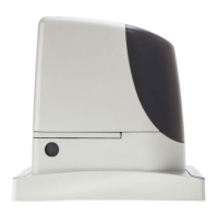
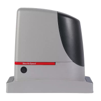
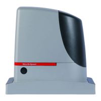
TheRUNproductlineincludesthefollowingproducts(table1-seeg.1).
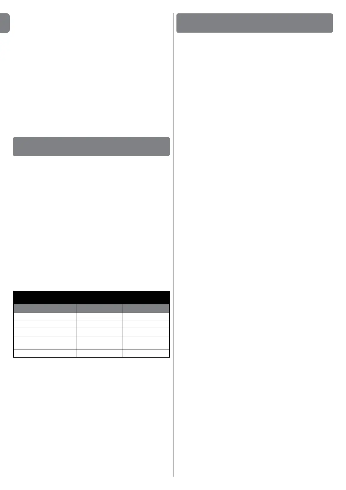
TABLE 1
comparison of basic characteristics of RUN gearmotors
Gearmotor type RUN400HS RUN1200HS
Type of limit switch electromechanical electromechanical
Max. gate length 14 mt 14 mt
Max. gate weight 300 kg 1200 kg
Maximum startup torque
(corresponding to force)
14.7Nm
(409N)
28.4Nm
(790N)
Motor 24V; 5500RPM 24V; 3100RPM
Note: 1kg = 9.81N, so that, for instance: 1390N = 142 kg
3
INSTALLATION
3.1 - Tests prior to installation
Caution!-TheinstallationofRUNmustbecarriedoutbyqualifiedper-
sonnelincompliancewithcurrentlegislation,standardsandregula-
tions,andthedirectionsprovidedinthismanual.
Before proceeding with the installation of RUN you must:
• Checkthatallthematerialsareinexcellentcondition,suitableforuseand
that they conform to the standards currently in force.
• Makesurethatthestructureofthegateissuitableforautomation.
• Makesurethattheweightanddimensionsofthegatefallwithinthespecified
operating limits provided in chapter 3.2 “Operating limits”.
• Checkthattheforcerequiredtostartthemovementofthegateislessthan
half the “maximum torque”, and that the force required to keep the gate in
movement is less than half the “nominal torque”. Compare the resulting val-
ues with those specified in the “Technical Characteristics”. The manufacturer
recommends a 50% margin on the force, as unfavourable climatic conditions
may cause an increase in the friction.
• Makesurethattherearenopointsofgreaterfrictionintheopeningorclosing
phases of the gates.
• Checkthatthereisnoriskofderailmentorthatthegatesmaycomeofftheir
guides.
• Makesurethatthemechanicalstopsaresturdyenoughandthatthereisno
risk of deformation even if the gate hits the mechanical stop violently.
• Makesurethatthegatesectionisbalanced,i.e.itmustnotmoveifleftstillin
any position.
• Makesurethattheareawherethegearmotorisfixedisnotsubjecttoflood-
ing; iff necessary, mount the gearmotor raised from the ground.
• Makesurethattheinstallationareaenablesthereleaseofthegearmotorand
that it is safe and easy to release it manually.
• Makesurethatthemountingpositionsofthevariousdevicesareprotected
from impacts and that the mounting surfaces are sufficiently sturdy.
• Componentsmustneverbeimmersedinwaterorotherliquids.
• KeepRUNawayfromheatsourcesandopenflames;inacid,salineorpoten-
tially explosive atmosphere; this could damage RUN and cause malfunctions
or dangerous situations.
• Ifthereisanaccessdoorinthegate,orwithintherangeofmovementofthe
gate, make sure that it does not obstruct normal travel and, if necessary,
provide an appropriate interlock system.
• Connectthecontrolunittoanelectricitysupplywithasafetyearthsystem.
• Connectthegatetotheprotectiveearthinaccordancewithcurrentlegisla-
tion.
• Provideadeviceontheelectricitysupplylinethatensurescompletedis-
connection of the automation mechanism from the grid. The disconnection
device must have contacts with an opening distance large enough to per-
mit complete disconnection under the conditions sanctioned by overvoltage
category III, in accordance with installation regulations. The device ensures
quick, safe disconnection from the power supply if needed, and must there-
fore be positioned in view of the automation mechanism. If, on the other
hand, it is located in a position which is not visible, there must be a system
forpreventingaccidentalorunauthorizedreconnectionwiththepowergridto
prevent this risk. The disconnection device is not supplied with the product.
3.2 - Operating limits
The “Technical Characteristics” chapter provides all the data needed to deter-
mine whether the products of the RUN line are suitable for the intended appli-
cation.
The structural characteristics of RUN make it suitable for use on sliding gates in
conformity with the limits indicated in tables 2 and 3.
The effective suitability of RUN to automate a particular sliding gate depends on
the friction as well as other correlated factors, such as ice, that could interfere
with the movement of the gate.
For an effective control it is absolutely vital to measure the force necessary
to move the gate throughout its entire run and ensure that this is less than
half of the “nominal torque” indicated in chapter 8 “Technical characteristics” (a
50% margin on the force is recommended, as unfavourable climatic conditions
may cause an increase in the friction); furthermore, it is necessary to take into
consideration the data indicated in tables 1 and 2 to establish the number of
cycles/hour, consecutive cycles and maximum speed allowed.

 Loading...