English – 15
4
ELECTRICAL CONNECTIONS
Only carry out electrical connections once the electricity supply to the system has been switched off. Disconnect any buffer
batteries present.
WARNING! – The cables used must be suitable for the type of installation. For example, an H03VV-F type cable is recommended
for indoor applications
Here follows a brief description of the electrical connections. Please refer to the “8.1. Adding or Removing Devices” paragraph for further infor-
mation.
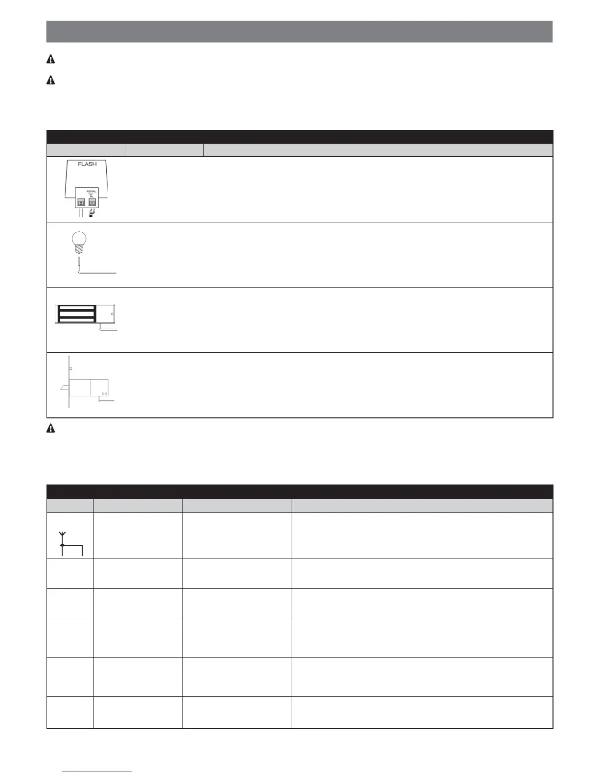
FLASH: this output is programmable (see paragraph 6.6.3) for connection of one of the following devices:
Table 6 - Types of electrical connections
Function Description
FLASHING LIGHT (EOQNFQ@LLDC@Rfk@RGHMF KHFGStNM SGDf%+ 2'tNTSOTS @-("$ f$+#"tk@RGHMF KHFGSB@MAD
connected with a car type 12V 21W lamp.
#TQHMFSGDL@MNDTUQDSGDTMHSk@RGDR@SHMSDQU@KRNER
“DOOR OPEN
INDICATOR”
OUTPUT
If programmed as “door open indicator” on the “FLASH” output a 24V max 5W indicator can be
connected to signal when the door is open.
It remains lit when the door is open and turns off when closed.
#TQHMFSGDL@MNDTUQDSGDHMCHB@SNQk@RGDRRKNVKXNMNODMHMF@MCE@RSNMBKNRHMF
SUCTION CUP If programmed as “suction cup” on the “FLASH” output a 24V max 10W suction cup can be
connected (versions with electromagnet only, without electronic devices).
When the door is closed, the suction cup is activated, locking the door. It is disabled during door
opening and closing manoeuvres.
ELECTRIC LOCK If programmed as “electric lock” on the “FLASH” output an electric lock with latch 24V max 10W
can be connected (versions with electromagnet only, without electronic devices).
During opening, the electric lock is activated for a brief interval to release the door and perform
the manoeuvre.
During closing, ensure that the electric lock engages mechanically.
NEVER USE DEVICES OTHER THAN THOSE SPECIFIED
4.1 - Electrical cable connections
Fig. 4 shows the electrical connections in a typical installation; WKHƄJXUHUHIHUULQJWRVWHSRIWKHLQVWDOODWLRQshows the electrical con-
nections to be made on the control unit.
Table 7 - Description of electrical connections
Function Type of cable Max. admissible length Description
Aerial (A)
1 shielded cable
(type RG58)
20m (recommended length:
below 5 m)
Connection input for the radio receiver aerial. The antenna is incorpo-
rated in the ELDC; alternatively an external antenna can be used, or a
section of wire already present on the terminal, which functions as an
antenna, can be left.
OPEN (C) 1 cable 2x0.5mm² 20m
Input for devices which control movement. It is possible to connect
“Normally Open” devices to this input. Exciting the input sends the Open
command.
SbS (C) 1 cable 2x0.5mm² 20m
Input for devices which control movement. It is possible to connect
“Normally Open” devices to this input. Exciting the input or pulling the
cord sends an SbS command (step-by-step).
STOP (D) 1 cable 2x0.5mm² 20m
Input for devices that block or shut down the manoeuvre in progress; by
setting the input accordingly, it is possible to connect “Normally Closed”,
“Normally Open”, constant resistance and OSE (Optical Safety Edge)
contacts. For further information about STOP, refer to par. “8.1”.
BLUEBUS
(B)
1 cable 2x0.75mm² 20m
This terminal enables the connection of compatible devices; all are con-
nected in parallel with just two wires conveying the electric power and
communication signals. For further information about BlueBUS, refer to
par. “8.1”.
FLASH (A) 1 cable 2x0.5mm² 20m
3GHRNTSOTSB@MADBNMMDBSDCSN@-HBD$+#"k@RGHMFKHFGSRDDSDBG-
MHB@KRODBHjB@SHNMR#TQHMFSGDL@MNDTUQDSGDTMHSk@RGDR@SHMSDQU@KR
of 0.5 s.
 Loading...