10 – ENGLISH
ELECTRICAL CONNECTIONS
Terminals Description
BLUEBUS
This terminal can be used to connect compatible devices, which are all connected in parallel with only two
wires carrying both the electric power and communication signals.
For further information on the BlueBUS, refer to the “Addressing of devices connected with the BlueBUS
system” paragraph.
STOP
Input for the devices that block or, if necessary, stop the manoeuvre under way. With suitable
arrangements, “Normally Closed” or “Normally Open” contacts, or xed resistor or optical devices can be
connected to the input.
For further information on the STOP function, refer to the “Modifying the STOP input conguration”
paragraph.
Sbs
Input for devices that control the movement in Step-by-Step mode; it is possible to connect “Normally
Open” contacts.
OPEN
Input for devices that control the opening movement only; it is possible to connect “Normally Open”
contacts.
CLOSE
Input for devices that control the closing movement only; it is possible to connect “Normally Open” contacts.
ANTENNA
Antenna connection input for radio receiver; the antenna is incorporated in the warning light; alternatively,
an external antenna can be used.
4.3 ADDRESSING OF DEVICES CONNECTED
WITH THE BLUEBUS SYSTEM
By means of addressing using special jumpers, the “BlueBUS”
system enables the user to make the control unit recognise the
photocells and assign the correct detection function.
The addressing operation must be done on both the TX and RX
photocells (setting the jumpers in the same way), while making
sure there are no other pairs of photocells with the same ad-
dress.
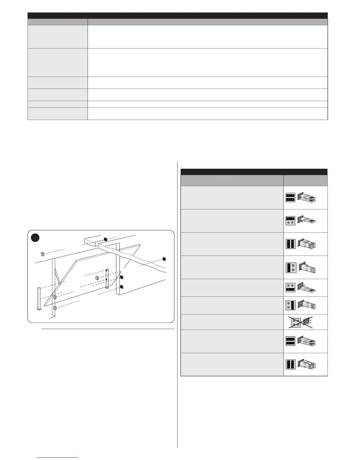
In systems for automated overhead doors, the photocells can
be connected as shown in the gure below.
FOTO 2
FOTO II
FOTO 2 II
FOTO 1
FOTO II
FOTO
15
m
At the end of the installation procedure, or after
photocells or other devices have been removed,
it is necessary to complete the learning procedure
(see the “Device learning” paragraph).
Table 6
PHOTOCELL ADDRESSES
Photocell
Position of the
jumpers
FOTO (PHOTO)
External photocell h = 50 activated during
the closing phase (stops and reverses the
gate’s movement)
FOTO II (PHOTO II)
External photocell h = 100 activated
during the closing phase (stops and
reverses the gate’s movement)
FOTO 1 (PHOTO 1)
Internal photocell h = 50 activated during
the closing phase (stops and reverses the
gate’s movement)
FOTO 1 II (PHOTO 1 II)
Internal photocell h = 100 activated during
the closing phase (stops and reverses the
gate’s movement)
FOTO 2 (PHOTO 2)
External photocell activated during the
opening phase
FOTO 2 II (PHOTO 2 II)
Internal photocell activated during the
opening phase
FOTO 3 (PHOTO 3)
Conguration NOT allowed
FA1
Photocell for opening command
(cut jumper A on the back of the TX and
RX boards)
FA2
Photocell for opening command
(cut jumper A on the back of the TX and
RX boards)
 Loading...