ENGLISH – 11
4.3.1 FT210B photosensor
The FT210B photosensor combines in a single device a force
limiting system (type C, in accordance with the EN12453 stand-
ard) and a presence sensor that detects obstacles on the line
of sight between the TX transmitter and RX receiver (type D, in
accordance with the EN12453 standard). In the FT210B photo-
sensor, the signals regarding the status of the sensitive edge
are sent through the photocell range, integrating the 2 systems
in a single device. The transmitting element located on the mov-
ing leaf is battery-powered, which eliminates visually unpleasant
connection systems; special circuits reduce battery consump-
tion, ensuring up to 15 years’ life (see estimation details in the
product’s instructions).
A single FT210B device combined with a sensitive edge (TCB65,
for example) allows for attaining the level of safety of the “prima-
ry edge” required by the EN12453 standard for all “types of use”
and “types of activation”.
The FT210B photosensor combined with the “resistive” sensitive
edges (8.2 kΩ) is safe against faults (category 3 pursuant to the
EN 13849-1 standard). It is equipped with a special anti-colli-
sion circuit to prevent interference with other detectors, even
not synchronised, and allows for adding other photocells; for
example, in case of transit of heavy vehicles, where a second
photocell is normally positioned 1 m above the ground.
l
Consult the FT210B instruction manual for further
information on the connection and addressing
methods.
FINAL CHECKS AND START-UP
5
5 FINAL CHECKS AND START-UP
It is advisable to position the leaf approximately halfway along
its path before starting the automation check and start-up phas-
es, so that the leaf is free to open and close.
5.1 POWER SUPPLY CONNECTION
a
The power supply connections must only be made
by qualied and experienced personnel possessing
the necessary requirements and in full conformity
to the laws, regulations and standards in force.
As soon as the product is powered, a few simple checks should
be carried out:
1. check that the BlueBus LED ashes regularly with one
ash per second.
2. make sure that the LEDs on the photocells (both the TX
and RX) also ash; the type of ashing is irrelevant, since
it depends on other factors.
3. check that the warning light connected to the FLASH out-
put is off.
4. check that the courtesy light is off.
If the above conditions are not satised, immediately switch
off the power supply to the control unit and carefully check the
electrical connections.
Further useful information on searching and diagnosing faults is
included in the “Troubleshooting” paragraph.
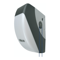
5.2 DEVICE LEARNING
Once the power supply has been connected, the control unit
must recognise the devices connected to the “BlueBUS” and
“STOP” inputs. Prior to this phase, LEDs “L1” and “L2” will ash
to signal that the device learning procedure must be performed.
m
The learning phase must be carried out even if no
device is connected to the control unit.
To do this:
1. simultaneously press and hold the
p
and
o
buttons
2. release the buttons when LEDs “L1” and “L2” start ash-
ing quickly (after roughly 3 seconds)
3. wait a few seconds until the control unit has completed the
device learning phase
4. once this phase terminates, the “Stop” LED must be lit
and LEDs “L1” and “L2” must switch off (LEDs “L3” and
“L4” could start ashing).
FUSE
L1L2L3L4L5L6L7L8
Flash
Bluebus
StopSbsOpenClose
LED
FUSE
L1
L2
16
The self-learning phase of the connected devices can be re-
peated at any time also after the installation, for example when-
ever a device must be added.
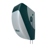
5.3 LEARNING OF THE DOOR OPENING AND
CLOSING POSITIONS
Once the devices have been learned, the control unit must rec-
ognise the door opening and closing positions, in addition to a
few optional positions.
There are 6 positions in total:
Before this phase, LEDs “L3” and “L4” ash (“Figure 17”) to
signal that the positions must be learned.
FUSE
L1L2L3L4L5L6L7L8
Flash
Bluebus
StopSbsOpenClose
LED
FUSE
L3
L4
17
 Loading...