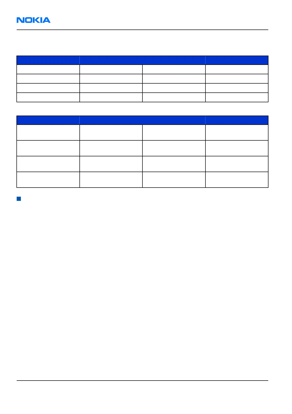
Receiver test points
Measure RF ASIC N7505 RF ASIC N7500 Expected Result
RXIP J7508 J7508 400 mVpp and 700mVDC
RXIN U87 J7509 400 mVpp and 700mVDC
RXQP J7510 No test point 400 mVpp and 700mVDC
RXQN J7529 No test point 400 mVpp and 700mVDC
Band RF ASIC N7505 RF ASIC 7500 Expected Result
GSM850 L7504 No test point 881,66771 MHz at
50dBm
GSM900 L7505 No test point 942,46771 MHz at
50dBm
GSM1800 L7501 C7515 1842,86771 MHz at
50dBm
GSM1900 L7500 C7514 1960,06771 MHz at
50dBm
Transmitter troubleshooting
General instructions for Tx troubleshooting
Context
• Tx troubleshooting requires Tx operation.
• Do not transmit on frequencies that are in use.
• Transmitter can be controlled in the local mode for diagnostic purposes.
• The best diagnostic tool for GSM transmitter testing is RF Controls, and for the WCDMA transmitter
testing Tx Control.
Tx IQ tuning and Tx power tuning can be also used in some cases.
• Remember that retuning is not a repair procedure.
The first set of steps instructs how to assemble the test setup. This setup is general for all Tx troubleshooting
tasks.
Alternative steps provide specific troubleshooting instructions for
Phoenix
service software. The first section
is for the EGSM900/GSM1800/GSM1900 bands and the latter for WCDMA.
Caution: Never activate the GSM or WCDMA transmitter without a proper antenna load. There should
be always 50 ohm load connected to the RF connector (antenna, RF-measurement equipment or at
least 2 watts dummy load), otherwise GSM or WCDMA PA may be damaged.
Steps
1. Connect a module jig to a computer with a DAU-9S cable or to a FPS-10 flash prommer with a modular
cable.
Make sure that you have a PKD-1 dongle connected to the computer parallel port.
RM-91; RM-92
Nokia Customer Care RF Troubleshooting and Manual Tuning Guide
Page 7 –18 COMPANY CONFIDENTIAL Issue 1
Copyright © 2006 Nokia. All rights reserved.
 Loading...