23 | Installation
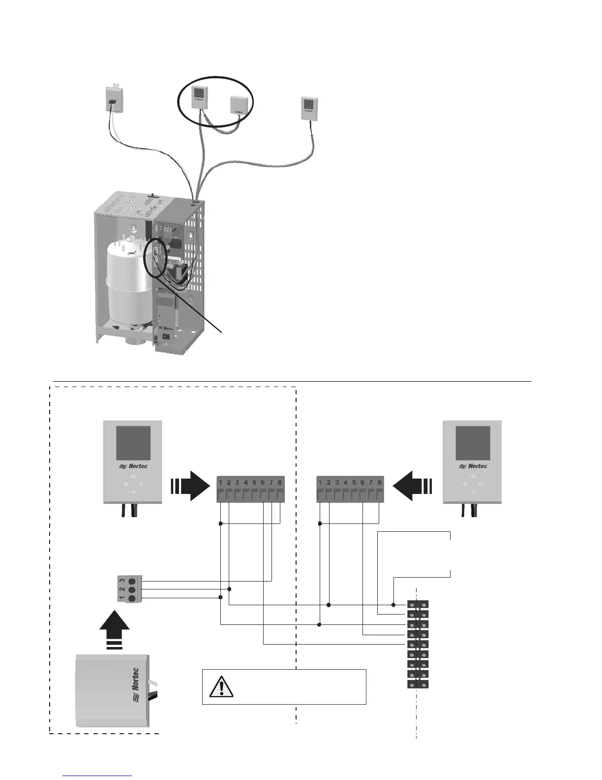
Modulating Control Wiring
Figure 21: Modulating Controls
1- 24 VAC
2 - On/Off Loop
3 - Ground
4 - Control Signal
5 - Limit Signal (NHTC only)
6 - 5 VDC
7 - Ground
8 - Blower Pack
9 - Blower Pack
1 - Ground
2 - 24 VAC
6 - Analog Out
8 - Temperature
Insert On/Off
controls or jumper
between 1 and 2
1510142 - Digital Wall Humidistat
1 - Ground
2 - 24 VAC
6 - Analog Out
7 - Analog In
8 - Temperature
2520266 - Digital Duct Humidistat
Package
N
H
T
C
Or
N
H
P
C
Analog Out - 3
24 VAC - 2
Ground - 1
E
x
t
e
r
n
a
l
Connect 24 VAC, terminal
1 of NHTC/PC to terminal
2 of controllers.
Figure 22: Digital Modulating Humidistats
Note: 1
2
3
4
5
Install On/Off controls or jumper between
terminal 1 and 2 of humidifier in order to run.
Terminal 1 is 24 VAC Hot, turn unit off to
avoid shorting while wiring.
High Limit Humidistat must be duct mounted.
It can be On/Off or modulating.
Control Humidistat can be mounted in space
or in return air duct and can be On/Off or
modulating.
The NHPC can only accept one modulating
signal.
Humidifier Terminal Strip
Air Provin
Switch
High Limit Humidistat
Control Humidistat
 Loading...