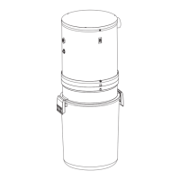
TUBING CONNECTIONS AT
POWER UNIT
This section refers to Figures 53 and 54.
Your VX Series power units are capable of being
connected to the intake vacuum trunk line from either
side. Select the intake connection to be used. Or some
installations may select connecting the vacuum air intake
into both intakes.
NOTE: Models VX475, VX550 and VX1000 will attach to
the upper intake connections. Models VX475C, VX550C
and VX1000C will attach to the lower intake connections.
See Figure 53 & 54.
1. Attach Utility Valve assambly in line with the vacuum
trunk line feeding into the power unit using the hose
clamp provided.
2. Cap off the unused intake tube with rubber cap
provided.
3. Attach exhaust tube to power unit using rubber cou-
pling and hose clamp provided.
4. Make sure all tubing connections are air tight.
5. The exhaust should NOT be vented into a wall,
ceiling or concealed space in the house. It is
recommended to vent the vacuum exhaust air to the
outside of the house. Exterior vented exhaust lines
should be terminated using Model 393 Wall Caps or
CI330 Wall Caps.
32
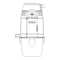
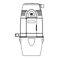
DIMENSIONAL CHART
Dimension VX475 VX550 VX1000
VX475C VX550C VX1000C
A 36.25” 39.50” 39.50”
B 10.75” 11.25” 11.25”
C 9.75” 10.50” 10.50”
FIGURE 53
FIGURE 54
CYCLONIC
BAGGED
 Loading...