9
WALL INLET INSTALLATION
MODEL CI370 WALL INLET (CF361 and
CF361F Rough-In)
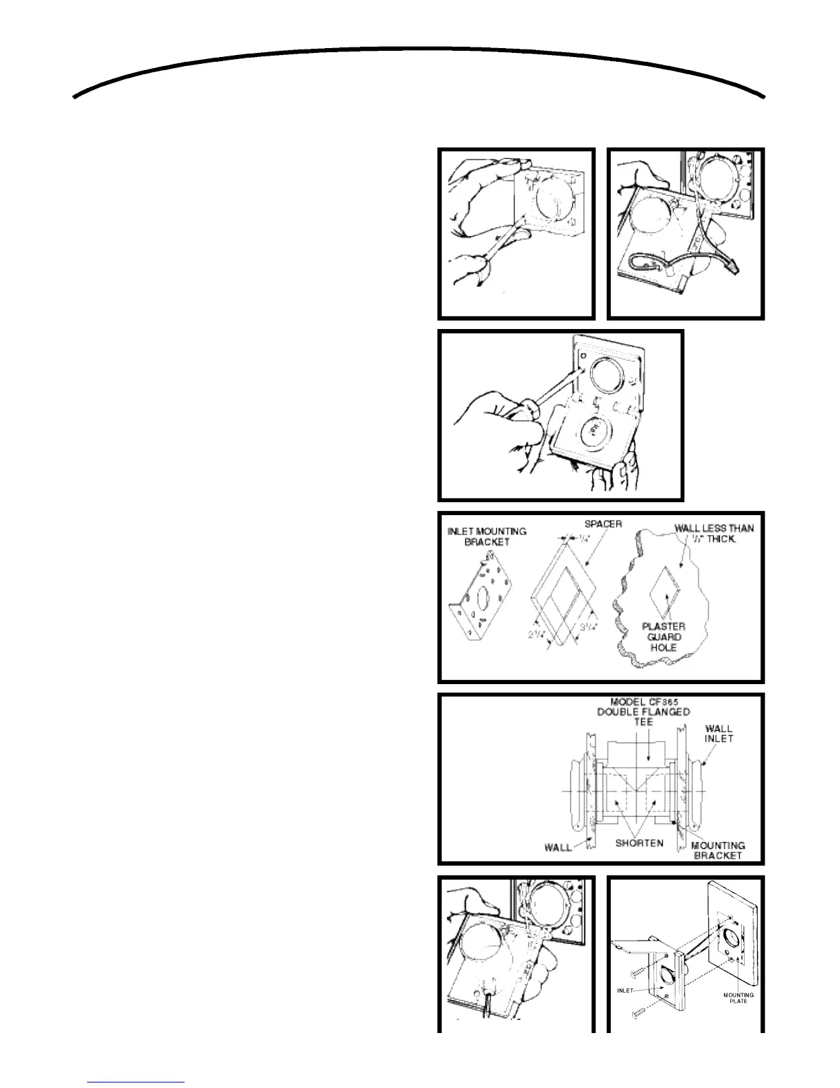
1. Remove the cardboard plaster guard.
2. Refer to Figure 14. For some drywall or panel con-
struction, the plaster frame will extend beyond the fin-
ished wall. In this case, remove plaster frame from
mounting bracket by removing mounting screws.
N O T E : When using the Model CF361 and CF361F inlet
bracket on walls thinner than 1⁄2", use a 1⁄4" spacer (not fur-
nished) between the wall and the inlet bracket. See Figure 17.
Spacer may be made from plywood, Masonite™, etc. Contact
cement may be used to hold spacer in place during assembly.
Configuration of spacer may vary depending upon installa-
t i o n .
3. Refer to Figure 15. Connect the red striped wire of the
2-conductor low voltage cable to the unused terminal
screw on the inlet. Connect the remaining wire to the
black pigtail wire. Cap off both wires using wire nut
( s u p p l i e d ) .
N O T E : The LED indicator light used in the CI370 is polarity
sensitive. If the 2-conductor cable used to connect the inlet to
the power unit does not have a polarity marking and the
CI370 is wired backwards, no damage will result; however,
the indicator will light RED instead of GREEN when the hose
is inserted into the inlet. To correct this condition, simply
reverse the 2-conductor connections at the CI370 inlet.
4. Guide excess wire back through the hole in inlet
bracket and flanged fitting
5. Refer to Figure 16. Place inlet into mounting bracket
and secure.
N O T E :
when wall inlets are installed in walls that are less
than 1⁄2" thick or when inlets are installed back-to-back in a
wall, the tube of the wall inlet may extend into elbow area of
the flanged fitting and cause blockage. Shorten the wall inlet
tube to prevent this condition. Refer to Figure 1 8 .
For extra thick walls, use Model 399 Extension Sleeve to
connect inlet to the flanged fitting.
MODEL 360 WALL INLET (CF361 and
CF361F R o u g h - i n )
1. Follow steps 1-2 as above.
2. Refer to Figure 19 Connect 2-conductor low voltage
wire to terminal screws on back of wall inlet.
3. Follow steps 4-5 as above.
MODEL 330 WALL INLET (CF329 Rough-in)
See Figure 20.
1. Connect 2-conductor low voltage wire to terminal
screws on back of wall inlet.
2. Align inlet mounting holes with holes in mounting plate.
3. Place inlet into mounting plate and secure with two
provided screws.
FIGURE 20 FIGURE 21
FIGURE 25 FIGURE 26
FIGURE 22
FIGURE 23
FIGURE 24
 Loading...