SYSTEM PLANNING LAYOUT (CONT’D)
page 3
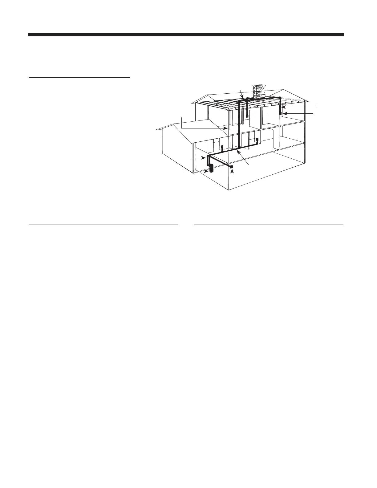
THE TWO-STORY HOUSE
A double-trunk line system is commonly
used in two-story houses. In the installation
shown at right, the power unit is mounted
in the basement. The intake tubing runs
up the basement wall and connects to the
main trunk line, which runs along the
unfinished basement ceiling. Two first-floor
inlets are connected to the basement
trunk line by vertical inlet lines run
through interior walls. In the center of the
house, a vertical branch line runs from
the basement trunk line, through stacked
closets, up into the attic. A second trunk
line runs across the attic and two branch
lines connect to inlet lines which are
dropped down through upstairs interior
walls. Refer to Figure 3.
FIGURE 3
LOCATING THE POWER UNIT
● Locate the power unit at the lowest possible position away
from the general living area in an accessible location for
emptying the debris pail.
● When planning, remember the power unit is equipped
with an inlet to service a garage, basement, utility room,
etc., wherever it is located.
● Locate the power unit within 6 feet (1.82 m) of a grounded
electrical outlet. Broan models VX3000C and VX6000C
and NuTone models VX475CC & VX550CC power units
require a 120 V, 15-amp dedicated branch circuit with a
NEMA 5-15R receptacle or 20-amp dedicated branch
circuit with a NEMA 5-20R receptacle. Broan model
VX12000C and NuTone model VX1040CC power units
require a 240 V AC, 20-amp dedicated branch circuit with
a NEMA 6-20 receptacle.
● Do not locate the power unit close to a source of extreme
heat (e.g.: water heater) or in an area with a high ambient
temperature (e.g.: attic, furnace room).
● If the power unit is located in a closet or a small
utility room, make sure the area is well-ventilated (e.g.:
with door louvers).
● Exhausting the power unit to the outside is recommended
for optimal performance. The exhaust should not be vented
into a wall, a ceiling or a concealed space in the house.
The exhaust line should be vented outside the home
using a Model V142 wall cap.
TUBING AND WALL INLET LOCATIONS
1. Locate inlets on interior walls, choosing central
locations which allow several rooms to be cleaned from a
single inlet using a minimum 30-feet (9.1 m) long hose.
2. The tubing installation should consist of a main trunk
line running from the farthest wall inlet to the power
unit location, with branch lines running to each additional
inlet. Keep all tubing lines as straight as possible and use
as few fittings as possible.
3. Beginning at the area farthest from the power unit, choose
a tentative inlet location. Measure 30 feet (9.1 m) from the
proposed inlet location to the farthest corner of the rooms
to be cleaned by that inlet to determine if inlet location is
proper. If working from blueprints (or building plans drawn
at 1/4" [0.64 cm] = 1 ft [30.48 cm] scale), use a 7½" chain
as your guide to determine inlet locations.
4. Locate inlets within six feet (1.8 m) of an electrical
receptacle to allow use of optional current-carrying hose.
5. Be sure inlets will not be blocked by doors or furniture.
6. Be sure inlets will not interfere with electrical, plumbing or
other mechanical installations.
7. Move tentative inlet location if necessary. Use the same
procedure to determine each additional inlet location,
always working toward the power unit.
 Loading...