MODEL V144 WALL INLET MOUNTING PLATE
(For use with V111 Series inlets)
Once the locations for wall inlets have been determined,
mount all inlet brackets.
1. To locate bracket on wall stud, measure approximately
18" (457 mm) up from finished floor level. (Height may
vary according to individual preference.)
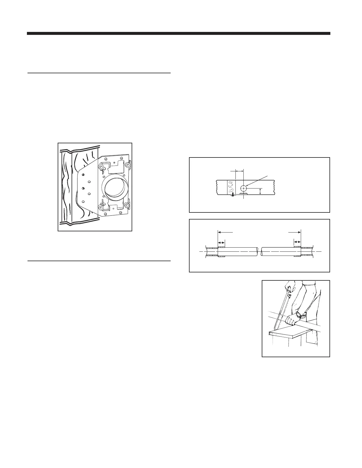
2. Glue elbow to mounting plate. Attach to stud as shown in
Figure 10.
INSTALLING THE TUBING
Use the following installation guidelines when installing tubing.
1. Start tubing installation at farthest inlet and work toward
the power unit.
2. Tubing run to the power unit should be as straight as possible.
3. When assembling sections with elbows and tees, make
sure the curve in the fitting is aligned so that the air flows
toward the power unit.
4. Branch lines should always join the trunk line from above
or from the same level. Never join a branch line from an
angle below the trunk line.
5. Run low-voltage wiring (Model V133) and secure wiring to
tubing as tubing is installed. Model V140 Tubing Strap can
be used to support long runs of tubing (position near
joists) and to clip wire along tubing. Secure tubing to joists
or studs. Leave approximately 6" (152 mm) of wire for
connection to each inlet.
6. Cut a 2½" (64 mm) diameter hole in sole plate, header or
stud directly in line with opening of inlet bracket fitting.
NOTE: Refer to Figure 11 for center line dimensions.
7. Refer to Figure 12. Measure length of tubing needed to
connect inlet to trunk line. Allow approximately 3/4" (19 mm)
of tubing for inserting into fittings.
8. Refer to Figure 13. Cut
tubing, keeping cut square.
page 5
INSTALLATION IN NEW CONSTRUCTION
 Loading...