9. Refer to Figure 14. Remove burrs from both inside and
outside of tubing.
10.Before cementing, pre-assemble section to inlet fitting,
check for proper length.
11. Refer to Figure 15. Apply PVC cement (Model V129) to
outside of tubing. Coat tubing approximately 1" (25 mm)
back. Make sure to keep cement from inside of tube.
12.Refer to Figure 16. Insert tubing into fitting with a twisting
motion to evenly spread cement. Be sure tubing is firmly
seated in fitting.
13.If fittings have been attached to tubing at the end opposite
the inlet bracket, be sure alignment is proper before
cement sets.
14.Refer to Figure 17. Tape wire to tubing to hold in place
and insert through hole in inlet bracket.
15.Connect each inlet line and branch line into main trunk
line. Complete low-voltage wiring as main trunk line is
continued back to power unit.
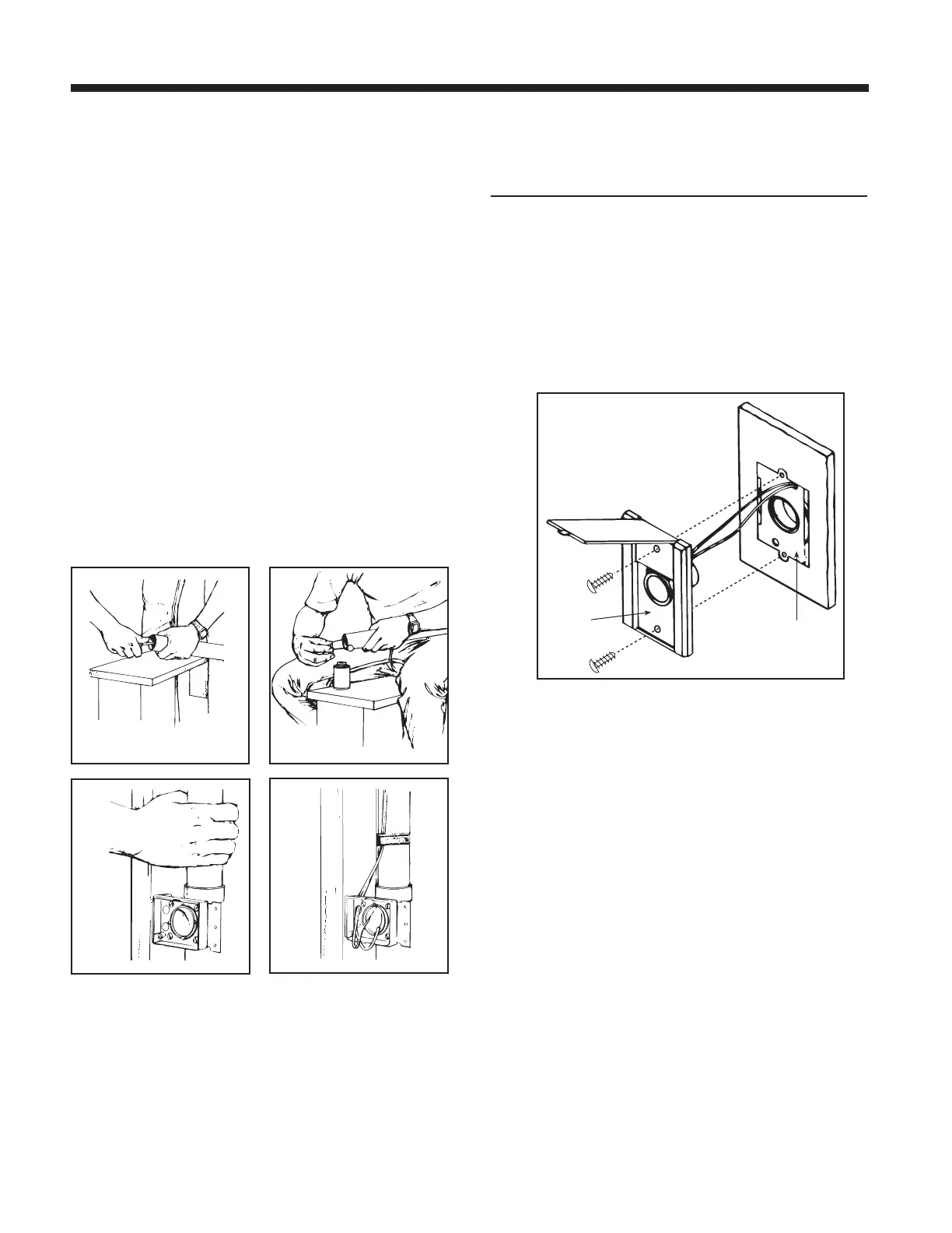
WALL INLET INSTALLATION
V111 Series Wall Inlet
(V144 Mounting Plate)
Refer to Figure 18.
1. Connect 2-conductor low-voltage wire to terminal screws
on back of wall inlet.
2. Align inlet mounting holes with holes in mounting plate.
3. Place inlet into mounting plate and secure with two
provided screws.
INSTALLATION IN NEW CONSTRUCTION (CONT’D)
page 6
 Loading...