Introduction > 12
R
EAR
VIEW
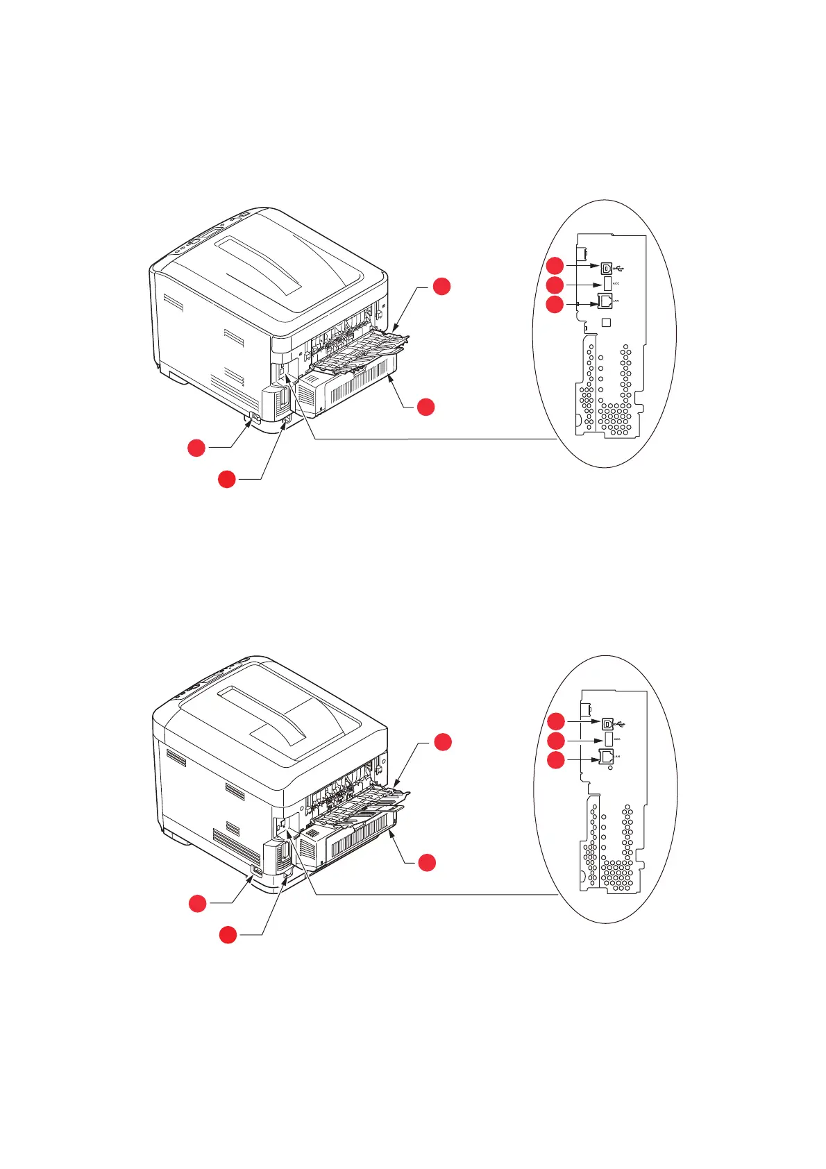
This view shows the connection panel, the rear output stacker and the location of the
optional duplex (two-sided printing) unit.
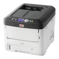
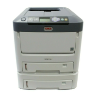
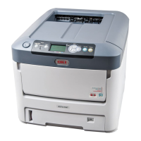
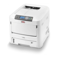
C612/ES6412
C712/ES7412
1. Main power switch.
2. AC power socket.
3. Duplex unit (when fitted).
4. Rear output tray (face up stacker).
5. USB interface.
6. ACC interface (host USB).
7. Network interface.
a
a. The Network Interface may have a protective “plug” which
must be removed before connection can be made.
1. Main power switch.
2. AC power socket.
3. Duplex unit (when fitted).
4. Rear output tray (face up stacker).
5. USB interface.
6. ACC interface (host USB).
7. Network interface.
a
a. The Network Interface may have a protective “plug” which
must be removed before connection can be made.
 Loading...