104
Analog Input Functions and Operating Procedures Section 3-6
Set Values and Stored
Values
Refer to 3-7-1 Adjustment Mode Operational Flow for further details.
Note For the CIO word addresses, n = CIO 2000 + (unit number x 10).
The input disconnection detection function can be used when the input signal
range is set for 1 to 5 V (4 to 20 mA).
3-6 Analog Input Functions and Operating Procedures
3-6-1 Input Settings and Conversion Values
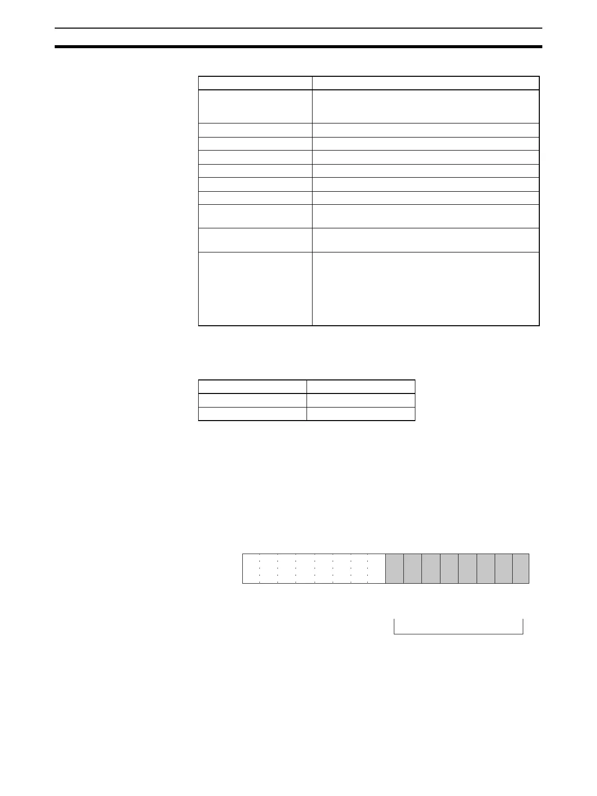
Input Numbers The Analog Input Unit converts analog inputs specified by input numbers 1 to
8 (1 to 4 for CJ1W-AD041-V1) only. To specify the analog inputs to be used,
turn ON from a Programming Device the D(m) bits in the DM Area shown in
the following diagram.
Note There are only four inputs for the CJ1W-AD041-V1.
The analog input sampling interval can be shortened by setting any unused
input numbers to 0.
Sampling interval = (1 ms) x (Number of inputs used) (See note.)
Item Contents
Input to be adjusted Sets input to be adjusted.
Leftmost digit: 2 (fixed)
Rightmost digit: 1 to 8 (1 to 4 for CJ1W-AD041-V1)
Offset (Offset Bit) When ON, adjusts offset error.
Gain (Gain Bit) When ON, adjusts gain error.
Down (Down Bit) Decrements the adjustment value while ON.
Up (Up Bit) Increments the adjustment value while ON.
Set (Set Bit) Sets adjusted value and writes to EEPROM.
Clr (Clear Bit) Clears adjusted value. (Returns to default status)
Conversion value for
adjustment
The conversion value for adjustment is stored as 16 bits
of binary data.
Disconnection detection 0: No disconnection
1: Disconnection
Alarm Flags Bit 12: Input value is outside adjustment limits
(in adjustment mode)
Bit 13: Input number setting error
(in adjustment mode)
Bit 14: EEPROM write error (in adjustment mode)
Bit 15: Operating in adjustment mode
(always 1 in adjustment mode)
Input signal range Voltage/current
1 to 5 V 0.3 V max.
4 to 20 mA 1.2 mA max.
15 14 13 12 11 10 09 08 07 06 05 04 03 02 01 00
Bit
D(m)
Input 2
Input 1
0: Not used
1: Used
Input 4
Input 3
Input 6
Input 5
Input 8
Input 7

 Loading...

