EasyManua.ls Logo

Omron CS1W-AD041-V1 User Manual

Omron CS1W-AD041-V1
427 pages
To Next Page IconTo Next Page
To Previous Page IconTo Previous Page
Page #82 background imageLoading...
Page #82 background image
59
Analog Input Functions and Operating Procedures Section 2-6
Setting 0: Not used (the conversion value is reset when the bit turns OFF)
1: Peak value hold function is used (held while ON)
CS1W-AD041-V1: Inputs 1 to 4
CS1W-AD081-V1: Inputs 1 to 8
For the CIO word addresses, n = CIO 2000 + (unit number x 10).
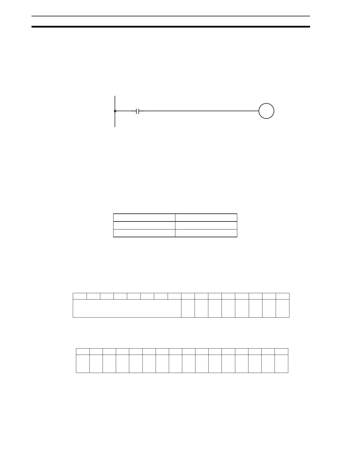
In the following example, the peak value hold function is in effect for input
number 1, and the unit number is 0.
When mean value processing is used together with the peak value hold func-
tion, the mean value will be held.
As long as the peak value hold function is in effect, the peak value hold will be
held even in the event of a disconnection.
When the load to the CPU Unit is disconnected, the Peak Value Hold Bits.
2-6-5 Input Disconnection Detection Function
When an input signal range of 1 to 5 V (4 to 20 mA) is used, input circuit dis-
connections can be detected. The detection conditions for each of the input
signal ranges are shown in the following table. (see note)
Note The current/voltage level will fluctuate according to the offset/gain adjustment.
The following bits turn ON when a disconnection is detected in each input.
When the connection is recovered, these bits turn OFF. Be sure to specify
these bits in the execution condition of the ladder program when using the dis-
connection detection function in the user program.
CS1W-AD041-V1/AD081-V1
CS1W-AD041-V1: Inputs 1 to 4
CS1W-AD161
For the CIO word addresses, n = CIO 2000 + (unit number x 10).
The conversion value during a disconnection will be 0000.
200000
Input condition
The maximum
conversion
data value is
held for input
number 1.
Range Current/voltage
1 to 5 V 0.3 V max.
4 to 20 mA 1.2 mA max.
Bit15 1413 12 111009 0807 060504 0302 01 00
n = 2000 + unit number x 10
Word n+9
Not used.
Input 6
Input 5
Input 8
Input 7
Input 2
Input 1
Input 4
Input 3
Bit 15 14 13 12 11 10 09 08 07 06 05 04 03 02 01 00
n = 2000 + unit number x 10
Input 2
Input 1
Input 4
Input 3
Input 6
Input 5
Input 8
Input 7
Input 10
Input 9
Input 12
Input 11
Input 14
Input 13
Input 16
Input 15
Word n+18

Table of Contents

Questions and Answers:

Omron CS1W-AD041-V1 Specifications

General IconGeneral
TypeAnalog Input Unit
Input Channels4
Resolution1/6000
Input Voltage Range0 to 5 V, 1 to 5 V, 0 to 10 V, -10 to +10 V
Input Current Range4 to 20 mA
IsolationPhotocoupler isolation

Summary

PRECAUTIONS

Safety Precautions

Essential safety guidelines for operating PLC systems and Analog I/O Units.

Application Precautions

Precautions for using PLC and Analog I/O Units in various applications and environments.

SECTION 1 System Design

1-1 Features and Functions

Overview of the features and functions of SYSMAC CS Series Analog I/O Units.

1-2 Basic Configuration

Explains the basic system configuration for CS-series and CJ-series PLCs.

SECTION 2 CS-series Analog Input Units

2-1 Specifications

Detailed specifications for CS1W-AD series Analog Input Units, including electrical and performance data.

2-4 Wiring

Covers terminal arrangements and wiring examples for CS-series Analog Input Units.

2-8 Handling Errors and Alarms

Troubleshooting guide for identifying and resolving errors and alarms in Analog Input Units.

SECTION 4 CS-series Analog Output Units

4-1 Specifications

Detailed specifications for CS1W-DA series Analog Output Units, including electrical and performance data.

4-7 Adjusting Offset and Gain

Procedures for calibrating the offset and gain of Analog Output Units in adjustment mode.

4-8 Handling Errors and Alarms

Troubleshooting guide for identifying and resolving errors and alarms in Analog Output Units.

SECTION 6 CS-series Analog I/O Unit

6-1 Specifications

Detailed specifications for the CS1W-MAD44 Analog I/O Unit.

6-6 Analog Input Functions and Operating Procedures

Explains input settings, conversion values, and functions for CS-series Analog I/O Units.

6-9 Adjusting Offset and Gain

Procedures for calibrating input and output offset and gain for the CS1W-MAD44.

Appendices

A Dimensions

Provides physical dimensions for CS-series and CJ-series units.

B Sample Programs

Illustrates sample programs for obtaining analog conversion values and setting output values.

Related product manuals