310
Exchanging Data with the CPU Unit Section 7-5
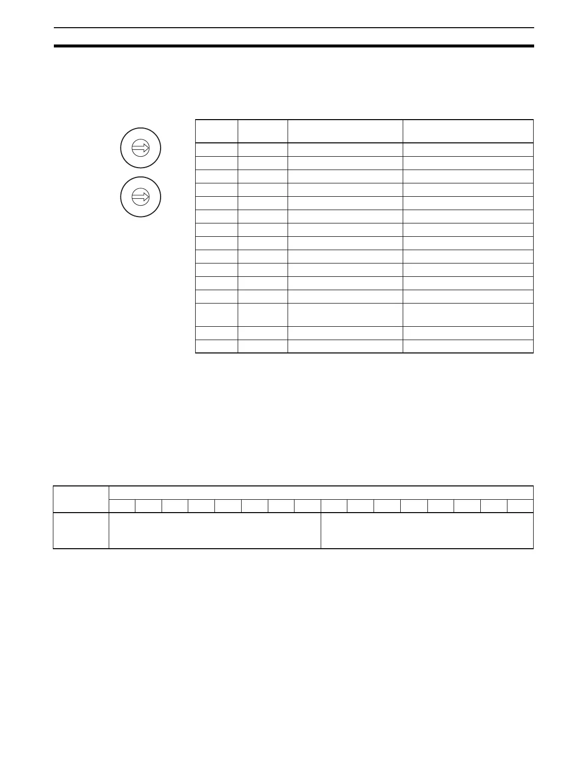
7-5-2 Unit Number Settings
The Special I/O Unit Area and Special I/O Unit DM Area word addresses that
each Analog I/O Unit occupies are set by the unit number switch on the front
panel of the Unit.
Note If two or more Special I/O Units are assigned the same unit number, a “UNIT
No. DPL ERR” error (in the Programming Console) will be generated (A40113
will turn ON) and the PLC will not operate.
7-5-3 Operation Mode Setting
The operation mode can be switched between normal mode and adjustment
mode (for offset gain adjustment) by changing the setting in bits 00 to 07 of
D(m+18).
Settings in D(m+18)
m = D20000 + (unit number x 100)
Switch
setting
Unit
number
Special/O Unit Area
addresses
Special I/O Unit DM Area
addresses
0 Unit #0 CIO 2000 to CIO 2009 D20000 to D20099
1 Unit #1 CIO 2010 to CIO 2019 D20100 to D20199
2 Unit #2 CIO 2020 to CIO 2029 D20200 to D20299
3 Unit #3 CIO 2030 to CIO 2039 D20300 to D20399
4 Unit #4 CIO 2040 to CIO 2049 D20400 to D20499
5 Unit #5 CIO 2050 to CIO 2059 D20500 to D20599
6 Unit #6 CIO 2060 to CIO 2069 D20600 to D20699
7 Unit #7 CIO 2070 to CIO 2079 D20700 to D20799
8 Unit #8 CIO 2080 to CIO 2089 D20800 to D20899
9 Unit #9 CIO 2090 to CIO 2099 D20900 to D20999
10 Unit #10 CIO 2100 to CIO 2109 D21000 to D21099
~~ ~ ~
n Unit #n CIO 2000 + (n x 10) to CIO
2000 + (n x 10) + 9
D20000 + (n x 100) to
D20000 + (n x 100) + 99
~~ ~ ~
95 Unit #95 CIO 2950 to CIO 2959 D29500 to D29599
MACH
No
.
10
1
10
0
0
9
8
7
6
5
4
3
2
1
0
9
8
7
6
5
4
3
2
1
DM word Bits
1514131211109876543210
D(m+18) Conversion time/resolution setting Operation mode setting
00: Normal mode
C1: Adjustment mode

 Loading...

