197
Analog Output Functions and Operating Procedures Section 5-6
5-6 Analog Output Functions and Operating Procedures
5-6-1 Output Settings and Conversions
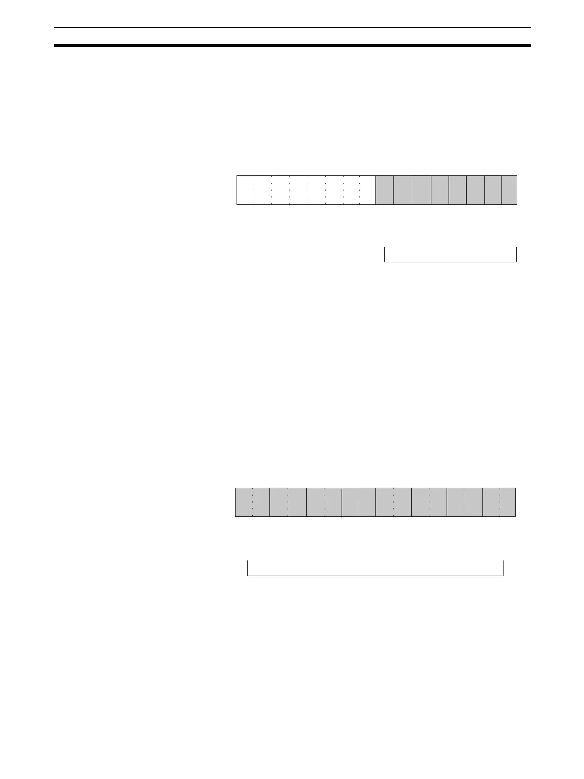
Output Numbers The Analog Output Unit converts only analog outputs specified by output
numbers 1 to 8 (1 to 4 for the CJ1W-DA041, and 1 and 2 for the CJ1W-
DA021). To specify the analog outputs to be used, turn ON from a Program-
ming Device the D(m) bits in the DM Area shown in the following diagram.
The analog output conversion cycle can be shortened by setting any unused
output numbers to 0.
Conversion cycle = (1 ms) (See note 3.) x (Number of outputs used)
Note 1. For the DM word addresses, m = D20000 + (unit number x 100).
2. Output numbers not used (set to 0) will be output at 0 V.
3. With the CJ1W-DA08V, the value will be 250
µs when set for a conversion
time of 250
µs and a resolution of 8,000.
Output Signal Range Any of four types of output signal range (–10 to 10 V, 0 to 10 V, 1 to 5 V, 4 to
20 mA, and 0 to 5 V) can be selected for each of the outputs (only voltage out-
put for the CJ1W-DA08V). (The output signal range for the CJ1W-DA08C is 4
to 20 mA only.) To specify the output signal range for each output, use a Pro-
gramming Device to set the D(m+1) bits in the DM Area as shown in the fol-
lowing diagram.
Note 1. For the DM word addresses, m = D20000 + (unit number x 100).
2. The 1 to 5 V output range and the 4 to 20 mA output range are switched
by changing the terminal connections.
3. When data memory settings have been carried out using a Programming
Device, be sure to either turn the power supply for the PLC OFF and then
15 14 13 12 11 10 09 08 07 06 05 04 03 02 01 00
Bit
D(m)
Output 2
Output 1
0: Not used
1: Used
Output 4
Output 3
Only outputs 1 and 2 are used
by the CJ1W-DA021.
Only outputs 1 to 4 are used
by the CJ1W-DA041
Output 6
Output 5
Output 8
Output 7
15 14 13 12 11 10 09 08 07 06 05 04 03 02 01 00
Bit
D(m+1)
Output 2
Output 1
00: −10 to 10 V
01: 0 to 10 V
10: 1 to 5 V (4 to 20 mA) (See note.)
11: 0 to 5 V
Output 4
Output 3
Only outputs 1 and 2 are used
by the CJ1W-DA021.
Only outputs 1 to 4 are used
by the CJ1W-DA041.
Output 6
Output 5
Output 8
Output 7
Note Only voltage output is enabled
for the CJ1W-DA08V. A range of
4 to 20 mA cannot be set.

 Loading...

