28
Components and Switch Settings Section 2-3
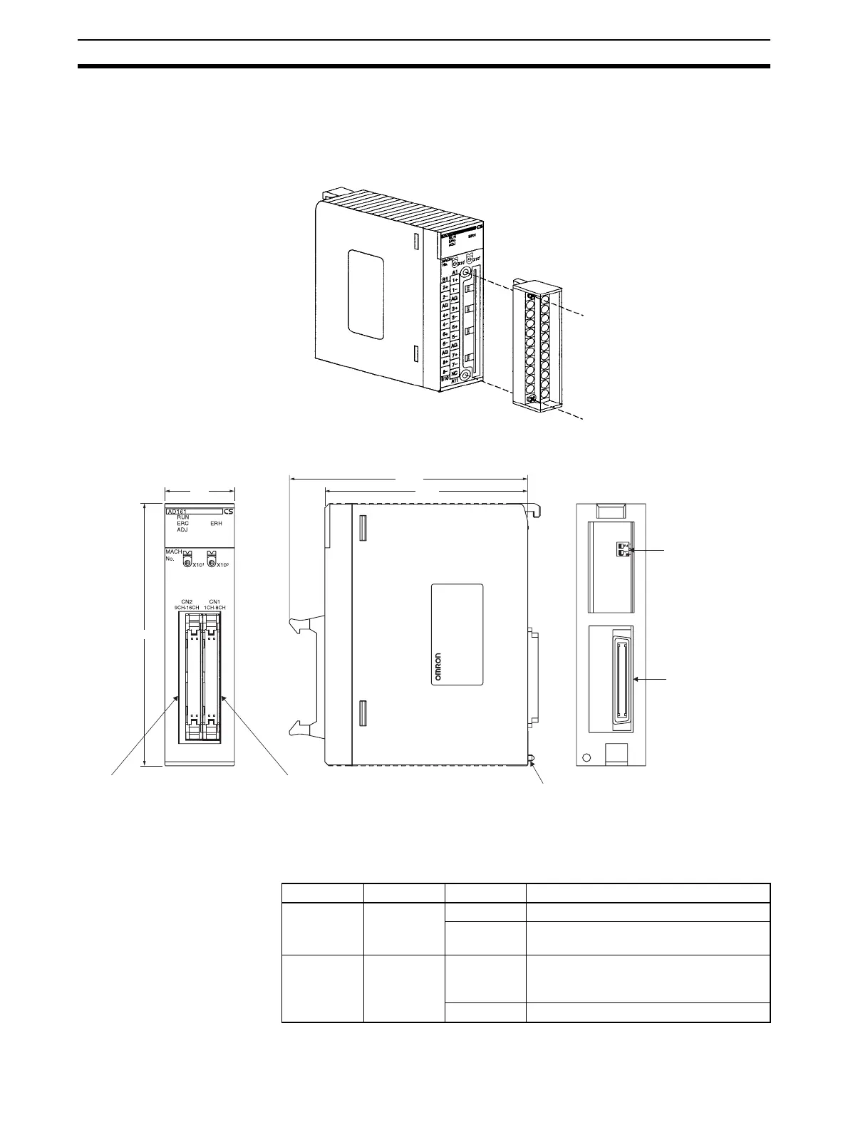
The terminal block is attached by a connector. It can be removed by loosening
the two black mounting screws located at the top and bottom of the terminal
block.
Check to be sure that the black terminal block mounting screw is securely
tightened to a torque of 0.5 N·m.
CS1W-AD161
2-3-1 Indicators
The indicators show the operating status of the Unit. The following table
shows the meanings of the indicators.
Fasten the mounting screw.
Fasten the mounting
screw.
34.5
118.03
100.5
130
Input connector 2
(Inputs 9 to 16)
Input connector 1
(Inputs 1 to 8)
Backplane mounting screw
Mode Switch
(two poles)
PC21 bus connecto
LED Meaning Indicator Operating status
RUN (green) Operating Lit Operating in normal mode.
Not lit Unit has stopped exchanging data with
the CPU Unit.
ERC (red) Error
detected by
Unit
Lit Alarm has occurred (such as disconnec-
tion detection) or initial settings are incor-
rect.
Not lit Operating normally.

 Loading...

