176
Operating Procedure Section 5-2
When the output for the connected devices needs to be calibrated, follow the
procedures in Offset and Gain Adjustment below. Otherwise, skip to Opera-
tion below.
Offset and Gain Adjustment
1,2,3... 1. Turn ON the power to the PLC.
Be sure to set the PLC to PROGRAM mode.
2. Turn ON the power to the external devices.
3. Set the mode to adjustment mode in the Special I/O Unit DM Area.
4. Turn the power to the PLC OFF and ON, or turn ON the Special I/O Unit
Restart Bit.
5. Adjust the offset and gain.
6. Set the mode to normal mode in the Special I/O Unit DM Area.
7. Restart the Analog Output Unit using its Special I/O Unit Restart Bit or turn
the power supply to the PLC OFF and ON.
Operation
Ladder program
• Write set values by means of MOV(021) and XFER(070).
• Start and stop conversion output.
• Obtain error codes.
Note Turn the external power supply ON and OFF while power is supplied to the
CPU Unit or simultaneously with the CPU Unit. Do not turn the external power
supply ON or OFF when power is not supplied to the CPU Unit.
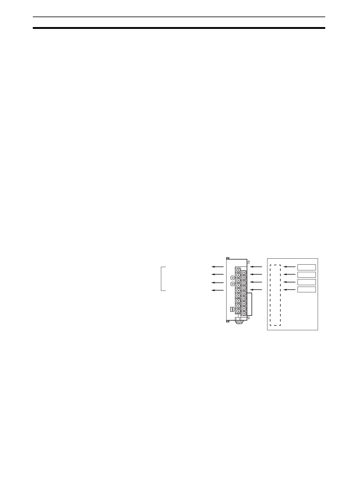
5-2-1 Procedure Examples
DA041
B1 A1
MACH
No.
x10
1
x10
0
RUN
ERC
ERH
ADJ
MODE
12
CJ1W-DA041 CJ-series CPU Unit
OUT1: 1 to 5 V
OUT2: 1 to 5 V
OUT3:
−10 to 10V
OUT4: Not used
Analog outputs
Unit No. 1
Ladder program

 Loading...

