22
Operating Procedure Section 2-2
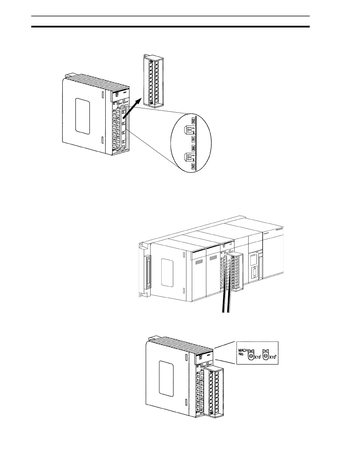
2. Set the voltage/current switch. Refer to 2-3-4 Voltage/Current Switch
(CS1W-AD041-V1/AD081-V1) for further details.
Note With CS1W-AD161, select voltage/current input by wiring the connector termi-
nals.
3. Mount and wire the Analog Input Unit. Refer to 1-2-1 Mounting Procedure,
2-4 Wiring or 2-4-4 Input Wiring Example for further details.
4. Set the unit number switch. Refer to 2-3-2 Unit Number Switch for further
details.
ON IN3 and IN4.
Pins IN1 to IN8 correspond to analog inputs 1 to 8.
E.g., To use voltage input for analog inputs 1 and 2,
turn OFF IN1 and IN2.
To use current input for analog inputs 3 and 4, turn

 Loading...

