42
Exchanging Data with the CPU Unit Section 2-5
CS1W-AD161
Note 1. The Special I/O Unit DM Area words that are occupied by the Analog Input
Unit are set using the unit number switch on the front panel of the Unit. Re-
fer to 2-5-2 Unit Number Settings for details on the method used to set the
unit number switch.
2. If two or more Special I/O Units are assigned the same unit number, a
“UNIT No. DPL ERR” error (in the Programming Console) will be generat-
ed (A40113 will turn ON) and the PLC will not operate.
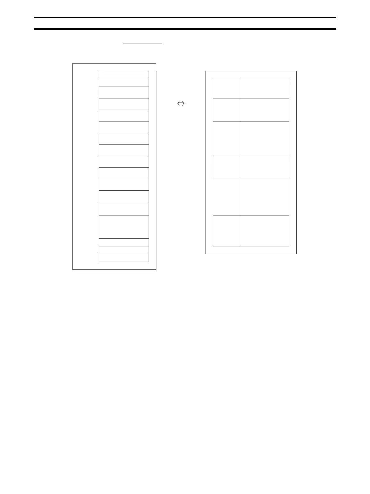
Allocated DM Area words
Unit #0 D20000 to D20199
Unit #1
D20100 to D20299
D (m)
Unit #2 D20200 to D20399
Unit #3 D20300 to D20499
D (m+1)
D (m+2)
Unit #4 D20400 to D20599
D (m+3)
Unit #5 D20500 to D20699
Unit #6 D20600 to D20799
D (m+18)
Unit #7 D20700 to D20899
Unit #8 D20800 to D20999
D (m+19)
Unit #9 D20900 to D21099
D (m+20)
Unit #10 D21000 to D21199
D (m+51)
Unit #N
D20000 + n x 100
to D20000 + n x 100
+99
D (m+52)
Unit #94 D29400 to D29599
Unit #95 m = 20000 + (Unit number x 100)
to to
to to
to
to
CS1W-AD161
Analog Input Unit
Special I/O Unit DM Area
Cannot be used.
Automatically
transfers settings
when the power
is turned ON or
the Special I/O
Unit Restart Bits
turn ON.
Initial data
Input conversion
enabled/disabled
Input signal range
Number of mean
value processing
sampling opera-
tions
Conversion time/
resolution, opera-
tion mode setting
Scaling data
Voltage/current
range specification
(enabled when us-
ing 1 to 5 V/4 to
20 mA)
CS-series CPU Unit

 Loading...

