4 - 9
4 Modbus Communications Procedure
E5@C Digital Temperature Controllers Communications Manual (H175)
4-4 Detailed Description of the Functions
4
4-4-1 Variable Read, Multiple
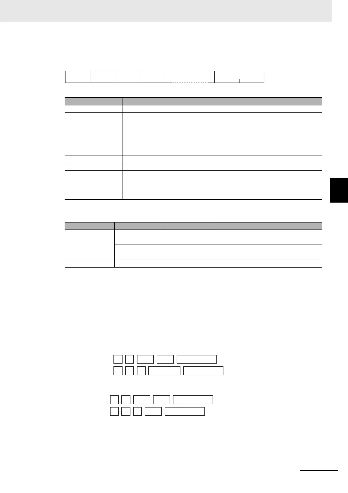
Response Frame
Response Code
Reading Undisplayed Parameters
It is possible to read the parameters that are not displayed due to display settings as well as the
parameters that are never displayed in the Controller.
• Example Command and Response
The following example shows the command and response when reading the process value (slave
address: H'01).
Process Value in 4-byte Mode
• Address: H’0000; Read data: H’000003E8 (100.0 °C)
Process Value in 2-byte Mode
• Address: H’2000; Read data: H’03E8 (100.0 °C)
Name Description
Slave address The value from the command frame is entered as-is.
Function code This is the received function code.
When the function ended normally, the function code is left as-is. When an error
occurred, the hexadecimal value of H'80 is added to the function code to indicate
that the response is an error response.
Example: Received function code = H'03
Function code in response frame when an error occurred = H'83
Byte count Contains the number of bytes of read data.
Read data Contains the number of setting data items that were read.
CRC-16 This check code is calculated with the data from the slave address to the end of the
data.
For details on the CRC-16 calculation, refer to CRC-16 Calculation Example in 4-1-1
Command Frame on page 4-2.
Function code Error code Error name Cause
H'83 H'02
Variable address
error
The read start address is incorrect.
H
'03
Variable data error The number of elements exceeds the
allowed range.
H'03
--- Normal completion No errors were found.
CRC-16
11
2
1
Slave
address
Function
code
Byte
count
0 to 212 (2 × 10⁶)
Read data (for the number of
elements)
H'03
Response: 01
03 04 00 00 03 E8 FA 8D(CRC-16)
Command: 01
03 00 00 00 02 C4 0B(CRC-16)
01 03 02 03 E8 B8 FA(CRC-16)
01 03 20 00 00 01 8FCA(CRC-16)
Response:
Command:

 Loading...


