7.IO-Link Connection Procedure
20
3
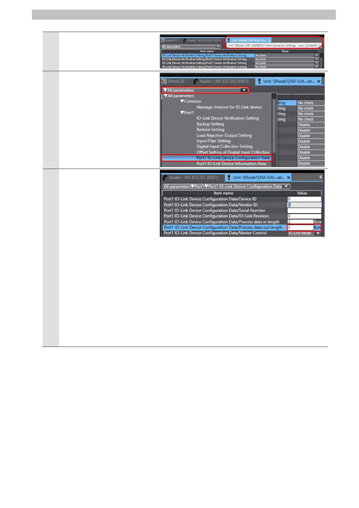
The Unit 1[Node1]:NX-ILM400
(N1)Unit Operation Settings Tab
Page is displayed.
Select
Port1 – Port1
IO-Link Device Configuration
Data from the pull-down list (just
above the column header "Item
name") to narrow down the
parameters.
The items of Port1 IO-Link
Device Configuration Data are
displayed.
Set the following items.
・Process data out length:
6 (Byte)
・Master Control:
IO-Link Mode (default)
*The process data length of
Signal Tower is "6 byte / 0 byte
(input from master / output to
master)"; however, in this
guide, the default value (2
bytes) is used for the process
data out length for Port 1 on
IO-Link Master Unit, which is
related to the process data
length "0 byte (output to
master)" of Signal Tower.

 Loading...


