7.IO-Link Connection Procedure
21
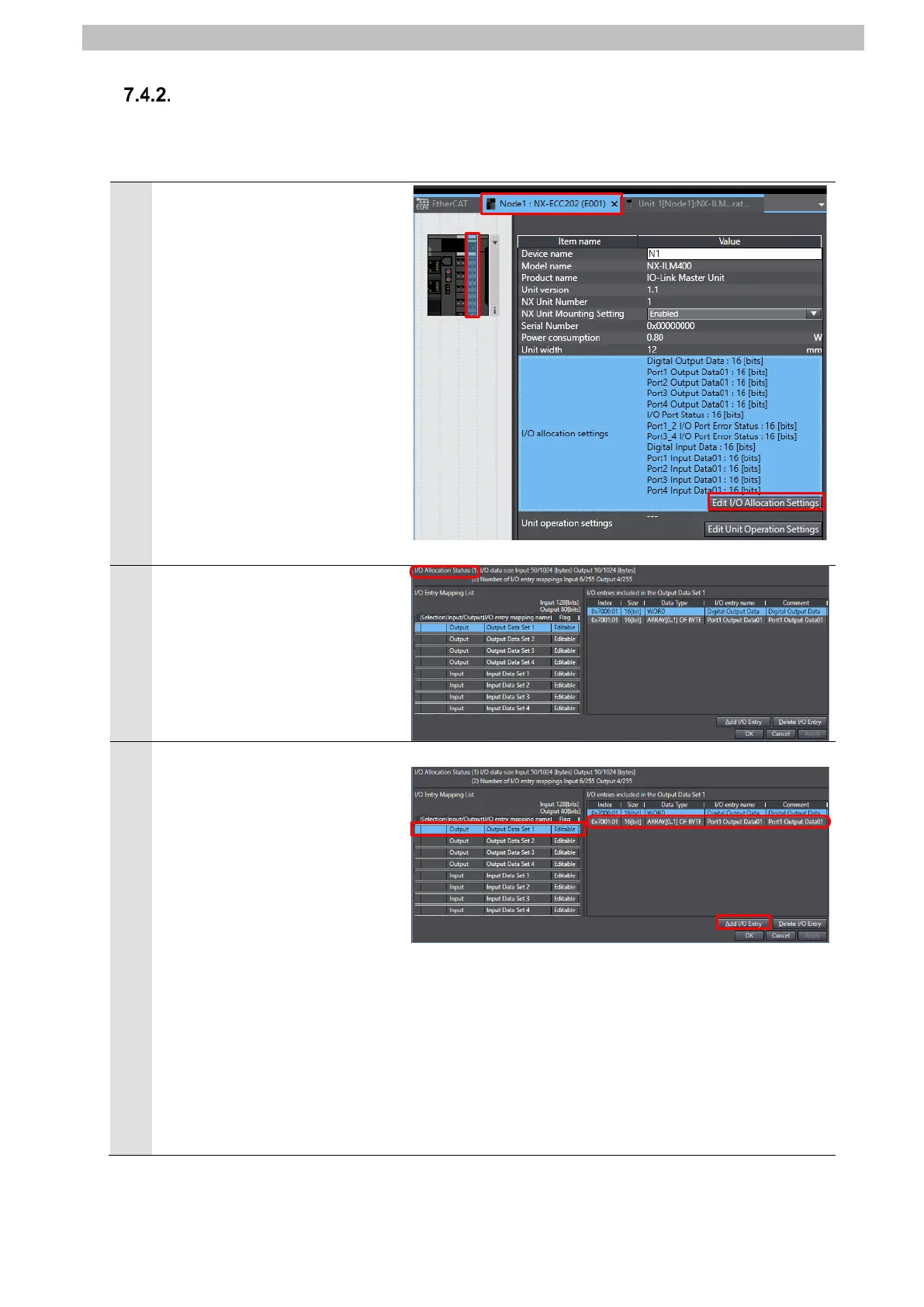
I/O Allocation Settings
Set I/O allocations for the IO-Link Master Unit.
In this guide, the data size of the output data area for Port 1 is set to 6 bytes.
Click the Node1 : NX-ECC202
(E001) Tab.
Select IO-Link Master Unit (NX
Unit number 1) and click Edit
I/O Allocation Settings.
The IO allocation status is
displayed.
3
Select Output Data Set 1 from
I/O Entry Mapping List displayed
on the left side of the dialog box.
The table of "I/O entries
included in the Output Data Set
1" is displayed on the right side
of the dialog box. Check that the
following I/O entry is set.
・0x7001:01 16[bit]
ARRAY[0..1] OF BYTE
Port1 Output Data01
Click Add I/O Entry.
*The data size of the output data
area for Port 1 is set to 2 bytes.

 Loading...


