EasyManuals Logo
Home>Omron>Controller>NX102 series

Omron NX102 series Network Connection Guide

Omron NX102 series
48 pages
To Next Page IconTo Next Page
To Previous Page IconTo Previous Page
Page #25 background imageLoading...
Page #25 background image
7IO-Link Connection Procedure
22
4
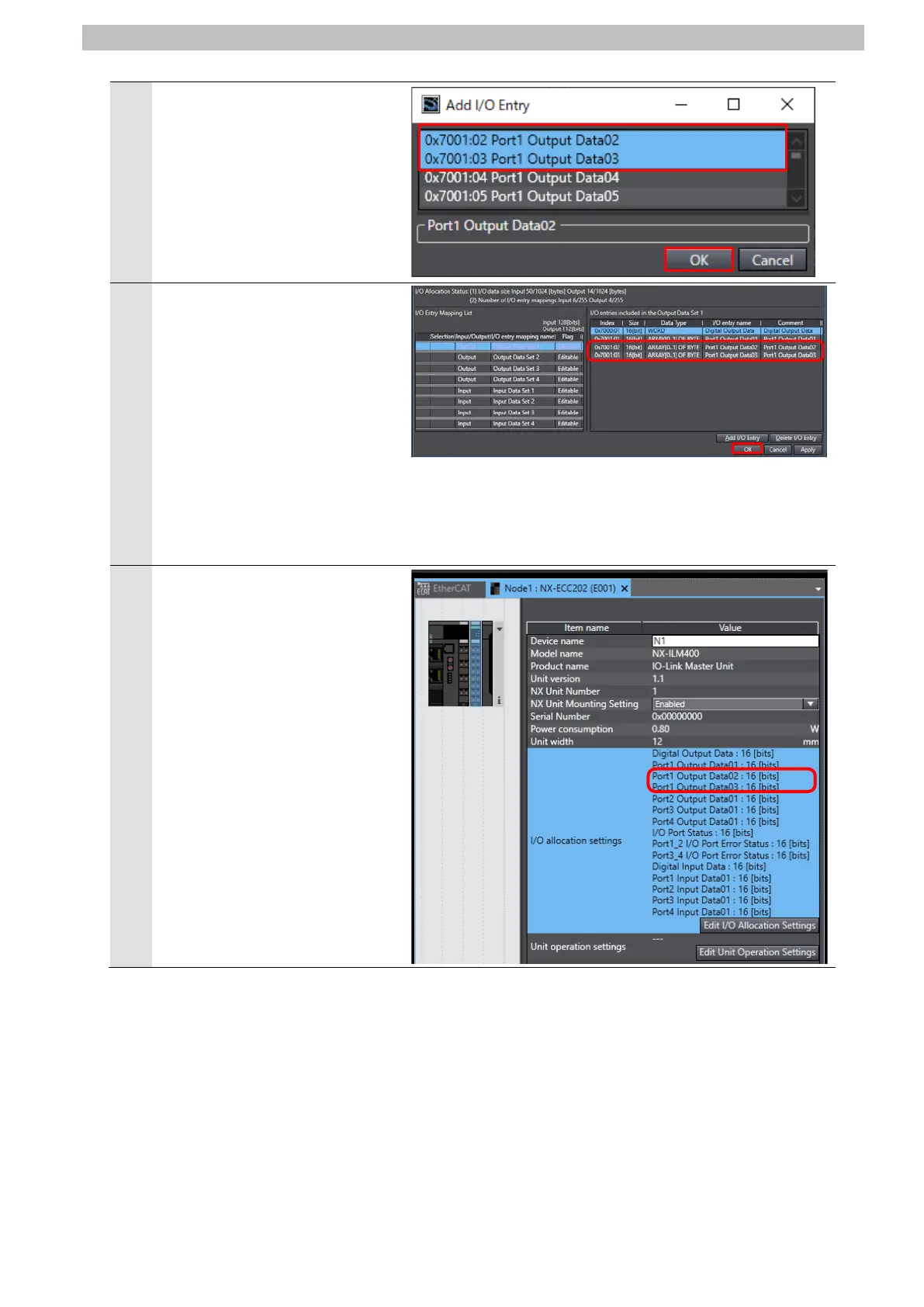
The Add I/O Entry Dialog Box is
displayed.
Select from 0x7001:02 Port1
Output Data02 to 0x7001:03
Port1 Input Data03 by holding
the shift key down.
Click OK.
5
Add the following I/O entries to
the table of "I/O entries included
in the Output Data Set 1".
0x7001:02 Port1 Output Data02
0x7001:03 Port1 Output Data03
Click OK.
*The data size of the output data
area for Port 1 is set to 6 bytes
in total.
6
Check that the following I/O
entries are added to the I/O
allocation settings Field.
Port1 Output Data02:16[bit]
Port1 Output Data03:16[bit]

Other manuals for Omron NX102 series

Questions and Answers:

Question and Answer IconNeed help?

Do you have a question about the Omron NX102 series and is the answer not in the manual?

Omron NX102 series Specifications

General IconGeneral
BrandOmron
ModelNX102 series
CategoryController
LanguageEnglish

Related product manuals