Omron TM Collaborative Robot S Series: TM12S and TM14S Hardware Installation Manual
The light module uses 4 of M3 screws to fix, and the recommended tightening torque is 1 Nm. For
higher accuracy on usages in demand, use both of the 2 ㎜ diameter openings with the positioning pins
to get the better steadiness. Users can replace the light module by applications in demand. The choice
depends on the torque load of the light module, the available load of the robot, the possible influence
the other light module made to the camera's field of view, and the electrical specifications.
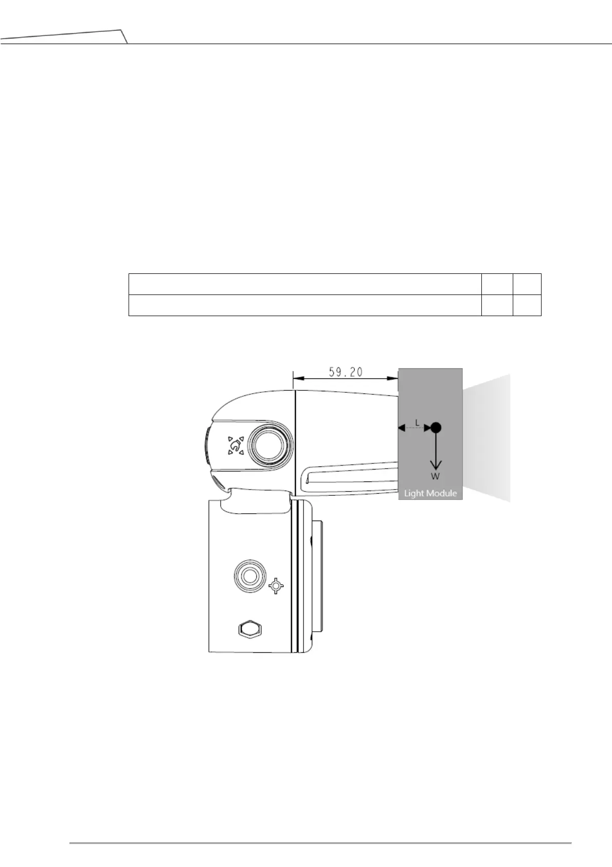
1. The torque load of the light module (M): this torque load must be lower than 900 kgfmm, which is
the available strength of the camera module M3 screw can be loaded.
Calculation formula: M = (L+59.2)*W
The weight of the light module
The center of gravity of the light module
Table 7: Reference of the Symbol and Unit in Calculation the Torque Load of the Light Module
Figure 28: Calculation the Torque Load of the Light Module
*All measures are in ㎜.
2. The maximum allowed payload of the robot: the weight of the light module must match the relative
relationship between the maximum allowed payload and the center of gravity offset distance. If the
robot end of the flange goes with additional applications, it is required to generate the equivalent
center of gravity for its position and total load from the combination of the light module and the
application tool as well as follow 4.2.1.4 Payload and Torque of this manual.
 Loading...