126
Configuration
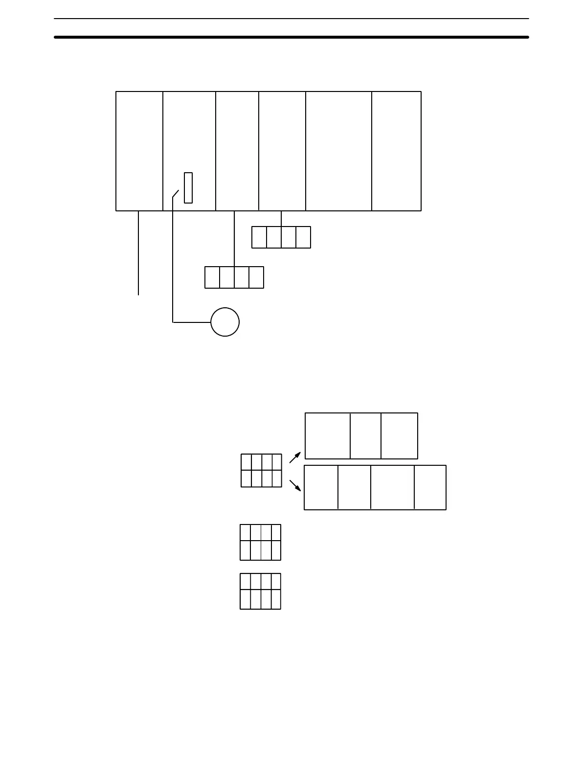
C200H
PC
IR 000
IN,
16 bits
SW1 (00010)
SW2 (00000)
Others
IR 002
IN,
16 bits
IR 003
IN,
16 bits
Thumbwheel SW (leftmost digits of
positioning data)
Thumbwheel SW (rightmost digits of
positioning data)
Driver/motor
Positioning
Control
Unit #0
The following is the minimum data required so that an alarm will not be gen-
erated.
HIGH-
SPEED
JOG
1 to F
LOW-
SPEED
JOG
1 to F
Initial
position
No.
0 to 19
Origin
prox.
speed
1 to F
DM 1082 2 0 0 0 Speed #1
DM 1083 0 5 0 0 Speed #2
DM 1098 0 0 0 6 Acceleration
DM 1099 0 0 0 6 Deceleration
Initial
speed
0 to F
ORIGIN
SEARCH
1 to F
ORIGIN
RETURN
speed
1 to F
DM 1000 1 0 0 0
DM 1001 1 2 1 2
Three consecutive words are transferred for positioning action #0. The bits of
IR 001, which is allocated to the Position Control Unit, are used as internal
relays. The next two words are input from thumbwheel switches connected to
Input Units allocated IR 002 and IR 003. Thus, when TRANSFER DATA is
executed with the beginning word designated as word 1, external data, which
has been prepared according to the data format for positioning action data,
can be used to achieve externally designated positioning actions.
Data Memory
Data To Be Transferred
TRANSFER DATA from External Switches Section 5–5