14 Programmable Relay ZEN
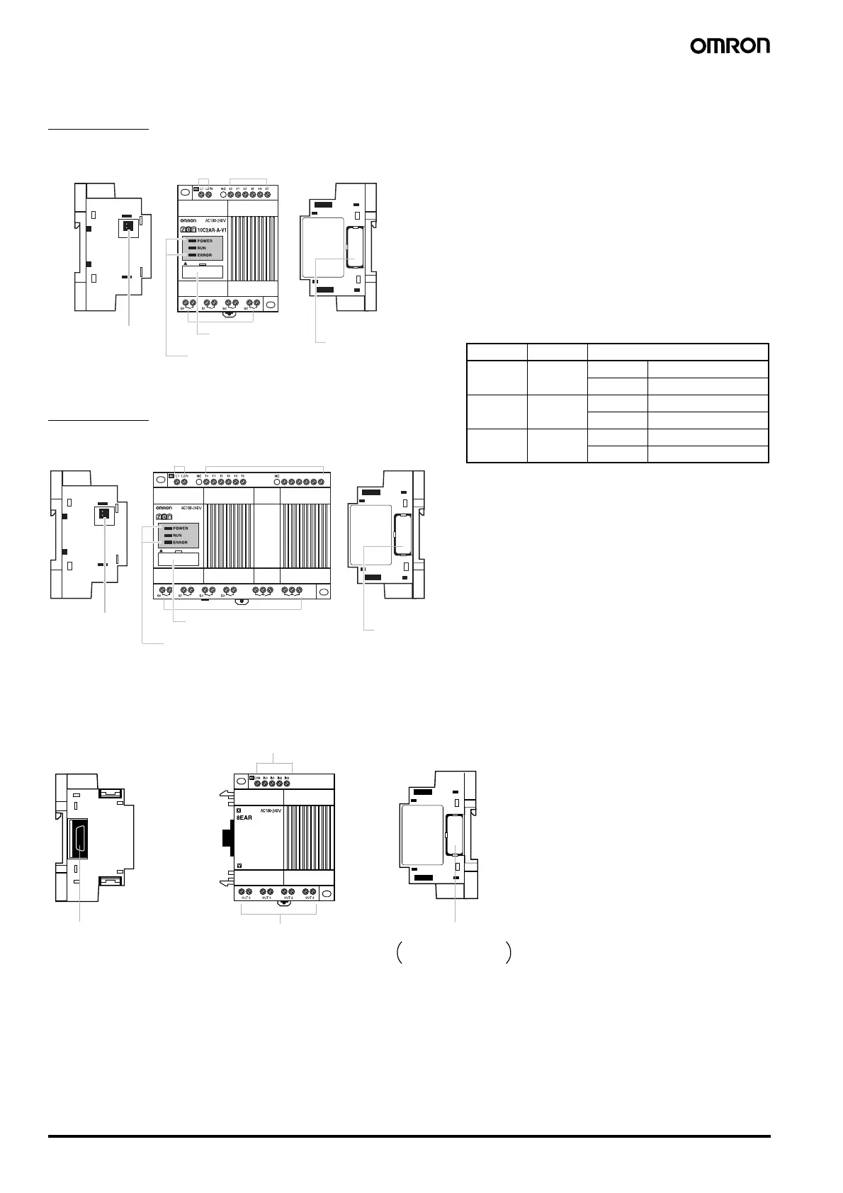
■ LED type
10 I/O Units
20 I/O Units
■ Expansion units
Left Side Front
Power supply
terminals
Input terminals
Right Side
Battery Unit connector
(Remove the seal to
connect the Battery
Unit.)
Output terminals
Personal computer
connector (also used for
Memory Cassette.)
LED indicators
Expansion I/O Unit
connector cover
Remove this cover to
connect Expansion I/O Unit.
I
6
I
7
I
8
I
9
I
a
I
b
20C2AR-A-V1
Q
4
Q
6
Q
5
Q
7
Left Side Front
Power supply
terminals
Input terminals
Right Side
Battery Unit
connector
(Remove the
seal to connect
the Battery Unit.)
Output terminals
Personal computer
connector (also used for
Memory Cassette.)
LED indicators
Expansion I/O Unit
connector cover
Remove this cover to
connect Expansion I/O Unit.
Left Side
Front
Input terminals
Right Side
Expansion Unit connector Output terminals
Expansion Unit connector cover.
Remove this cover to
connect Expansion I/O Unit.
Indicators
Name Color Meaning
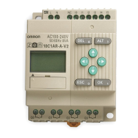
POWER Green Lit Power supplied
Not lit No power
RUN Green Lit Operating (RUN)
Not lit Stopped (STOP)
ERROR Red Lit Error
Not lit Normal
AUDIN - 8, avenue de la malle - 51370 Saint Brice Courcelles - Tel : 03.26.04.20.21 - Fax : 03.26.04.28.20 - Web : http: www.audin.fr - Email : info@audin.fr
 Loading...