Programmable Relay ZEN 9
6 Display Settings
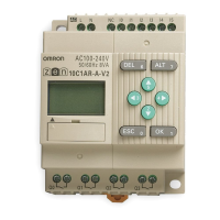
7 Analog Comparator Operation Example
8 Timer/Counter Comparator Operations
9 Specifications for Button Input Bits
Backlight Terminal mode
switching
L0: Backlight does not turn ON (ignored if already ON).
L1: Backlight turns ON
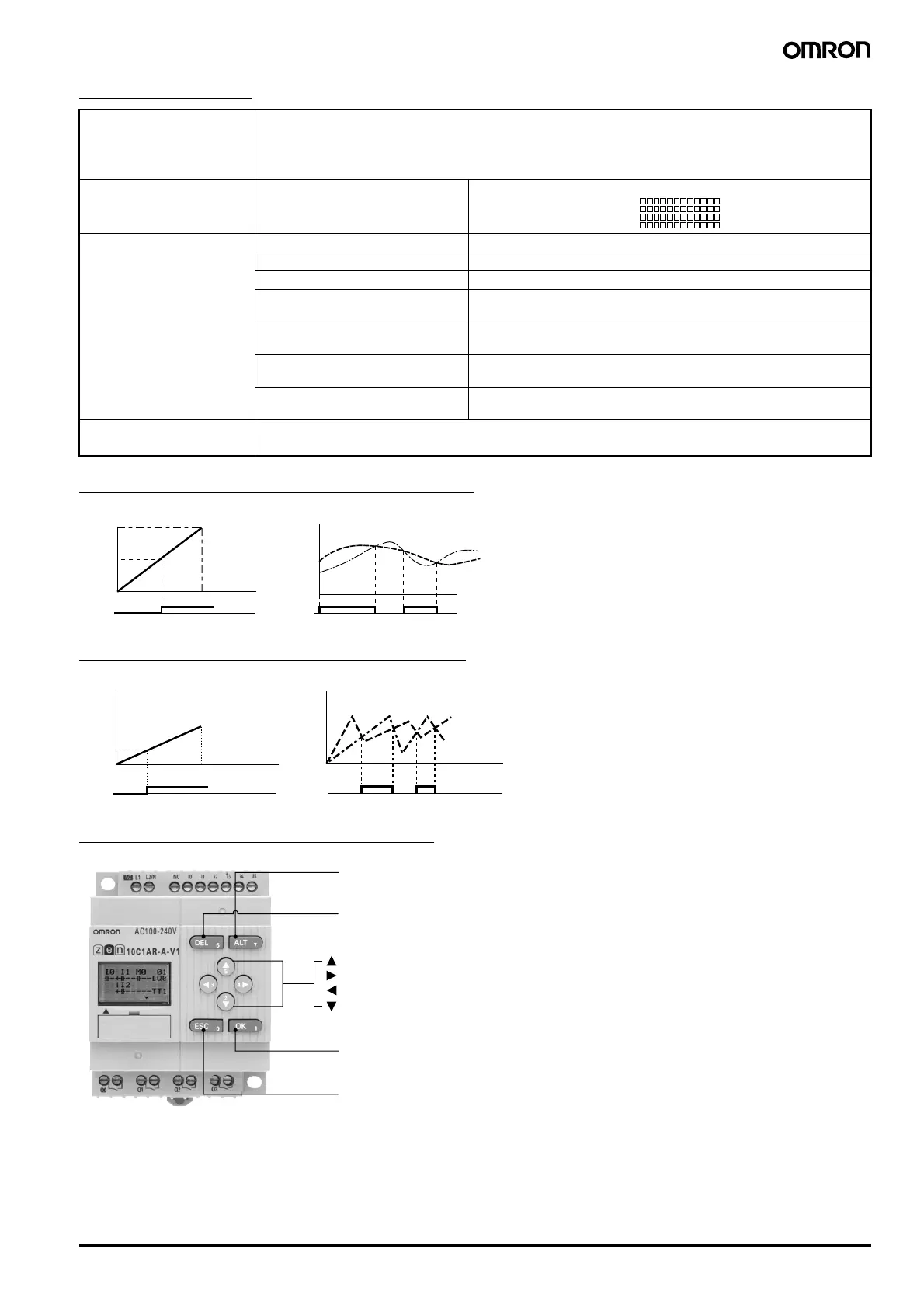
L2: Terminal mode switching (backlight not ON)
L3: Terminal mode switching (backlight ON)
Display start position X (digit): 00 to 11
Y (line): 0 to 3
Display object CHR Characters (up to 12 characters - English, numerals, symbols)
DAT Month/day (5 digits @@/@@)
CLK Hour/minute (5 digits @@:@@ )
I4 to I5 Analog-converted value
(4 digits @@:@)
T0 to Tf Timer present value
(5 digits @@.@@)
#0 to#7 Holding timer present value
(5 digits @@.@@)
C0 to Cf Counter present value
(4 digits @@@@)
Monitoring A: Can read settings during operation.
D: Cannot read settings during operation.
X00 X11
Y0 to Y3
Setting
10.0
5.2
00.0
0.0
Setting
10.0
0.0
A0 bit A1 bit
a.
When input 1 ≥ 5.2 V
b.
When input 1 ≤ input 2
Input 1
(I4 converted
display)
Input voltage
10.0V
Time
Input 2
(I5 converted
display)
Input 1
(I4 converted
display)
Setting
99.99
12.20
00.00
Setting
9999
0000
P0 bit P1 bit
a. When Timer 0 (T0) ≥ 12 min 20 s b. When Counter 1 (C1) is
≤
Counter 2 (C2).
00 min 00 s 12 min 20 s
Timer present
value
Counter 1 (C1)
Counter 2 (C2)
ALT
Button input 7 (B7)
DEL
Button input 6 (B6)
OK
Button input 1 (B1)
ESC
Button input 0 (B0)
Button input 5 (B5)
Button input 4 (B4)
Button input 3 (B3)
Button input 2 (B2)
AUDIN - 8, avenue de la malle - 51370 Saint Brice Courcelles - Tel : 03.26.04.20.21 - Fax : 03.26.04.28.20 - Web : http: www.audin.fr - Email : info@audin.fr
 Loading...