I
2.
Construct exhaust system to
prevent
damage
from
leakage
and vibtation.
Use
automotive type
hangels
and connections under the vehicle.
Use
an insulating thimble where
exhaust piping
passes
through a
partition
or
floor
of
flammable
rnaterial.
Exhaust
lines may
be asbestos wrapped
to reduce heat
radiation within
the
compadment.
Terminate the exhaust outlet aft
of
the set com-
partment
and extend to
perimeter
of vehicle
so
DEADLY
exhaust
fumes will
not enter
vehicle
undet ordinary
conditions
of
driving
or
parking.
lasoline
Iiller
Vacu-Flo sctoll.
Do not install
the exhaust outlet
closer than three
feet lrom
the
spout- Do not
pipe
exhaust into
When
installing mufflers, other than those
supplied
with the
unit or if
the exhaust system is excessively
complicated, the
exhaust
back
pressure should
be
checked.
Exhaust
back
pressure
at rated load, measured
at the exhaust manifold,
should
not
exceed 2
in.
Hg.
(Mercury colurnn).
Where
a tapped hole is not
provided,
the
manifold
and/or a
pipe
coupling may be drilled and
tapped.
After
measurement
is made,
plug
the
hole
with
an
ordinary
pipe plug.
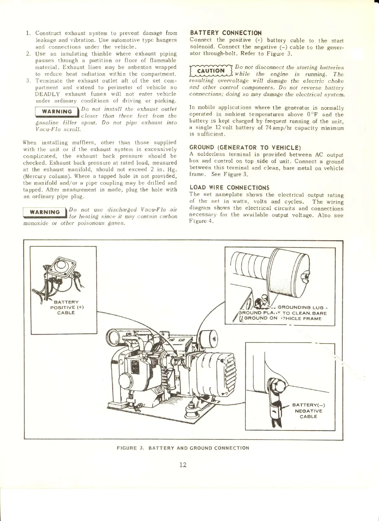
BATTERY
CONNECTION
Connect
the
positive (+)
battery
cable
to
the
start
solenoid. Connect
the
negative (-) cable
to the
gener-
ator
th.ough-bolt. Refer
to Figure
3.
Do
not disconnect
the sta
inE balleries
while
the engine
is runninp.
The
.esultirg
overvoltage
will
danage the electric
choke
and
other
control
components.
Do
not
revetse
battery
connections;
doinS so
ney damage
the eleclrical sysfem.
In
mobile applications
where
the
generator
is
notmally
operated
in ambient
temperatures above
OoF and
the
battery
is kept charged
by frequent running
of the
unit,
a single
12volt
battery
of 74
amp/ht
capacity
minimum
is
sufficient.
GROUND
(GENERATOR
TO VEHICLE)
A
solderless
terminal
is
provided
between
AC
output
box and
control
on top side
of unit. Connect
a
ground
between
this terminal
and clean,
bare
metal
on vehicle
frame.
See Figure
3.
LOAD WIRE
CONNECTIONS
The
set
nameplate shows
the electrical
output rating
of the
set in watts,
volts and
c5rcles.
The
wiring
diagram shows
the electrical
circuits
and connections
necessary
for
the available
output voltage.
Also
see
Fi
eure
4.
1.
3.
I
rarNiirc
| ?'
-lor
monoxide ot other
not use discha.ged Vacu-F lo at
heatin!
since
it may
contain
carbon
poisonous
dases.
€ROUNDIN6
LUO
/OROUND
PLA, rt
TO CLEAN,BARE
/ A.sRouNo
oN
.=HtcLE
FRAME
-_-l
FIGURE
3.
BATTERY
AND
GROUNO CONNECTION
L2
 Loading...


