!
CARBURETOR
ADJUsTMENT
The
carburetor
(Figuie
8) has
a high
speed fuel
main
adjustment
(needle
A)
and a fuel
idle adjustment
(needle
B).
Adjust
the calburetor
to
obtain
the corfect fuel-to-air
mixture for
smooth,
efficient
operation.
The
carburetor
should
be adjusted
in two steps
-
first
the load
adjust-
ment
and then
the idle
adjustment.
IMPORTANT;
II the carburetot
is completely
out ol
adjustment
so
tfie enlline
will
not tun,
open both
needle
valves 1
to 1-1/2
tutns
otl
their
seats
to permit
starting.
Do
not force
the needle
yalyes
a{ainsf
tleir seats.
Tfiis
will
bend the
needle.
Before adjusting
the
carburetor,
be sure the
ignition
s],stem
is working properly
and
the
governor
is adjusted.
Then
allow the engine
to
warm up.
1.
With no
load, turn
the
idle
adjustment
out until
the
engine
speed
drops slightly
below
normal.
Then
turn the
needle
in until the engine
speed
retums
to normal.
2. Apply
a full
load to the ergine.
3. Carefully
turn
the main adjustmeot
in
until speed
drops slightly
below
normal. Then
turn needle
out
until speed returns
to normal.
THROTTL
E
STOP
SCRE
THIS
OISTAN CE
t/32"
AT
NO LOAO
MAIN
FUEL
AOJUSTTIE
NT
YLO ROO EXTENDIXG
DOWX THROUGH LOIVER
SHROUO PAN
FIGURE
8.
CARBURETOR
ADJ
USTM
ENTS
Alternote
Method: Use
When
There is
No Lood
Adiust-
rnent
Pos
sible.
1. Start the engine and allow
it to
warm
up.
2.
Push in on the
governor
mechanism to slow the
unit
down
to about 800-900rpm.
3. Set the idle adjustrnedt screw for even
operation
(so the engine
is
running smoothly).
4.
Release
the governor
mechanism
to
allow
the
engifle
to accelerate.
If
the
engine accelerates
evenly
and
without
a
lag, the
main adjustment
is correct.
If
not,
adjust the
needle
outward
about
l/2 tltn
and
again
slow
down the
engine
and
release
the rnechanism.
Continue
until the
ensine
accelerates
evenly
and
without
a tirne
lag after
releasing
the governor.
With
the
carburetor
and governor
adjusted,
set the
throttle
stop screw,
Figure
8, to
allow 1/32
inch clear-
ance
to the stop pin
with the
engine
operating
at no
load, This prevents
excessive
hunting
when
a large
Ioad is
suddenly
removed.
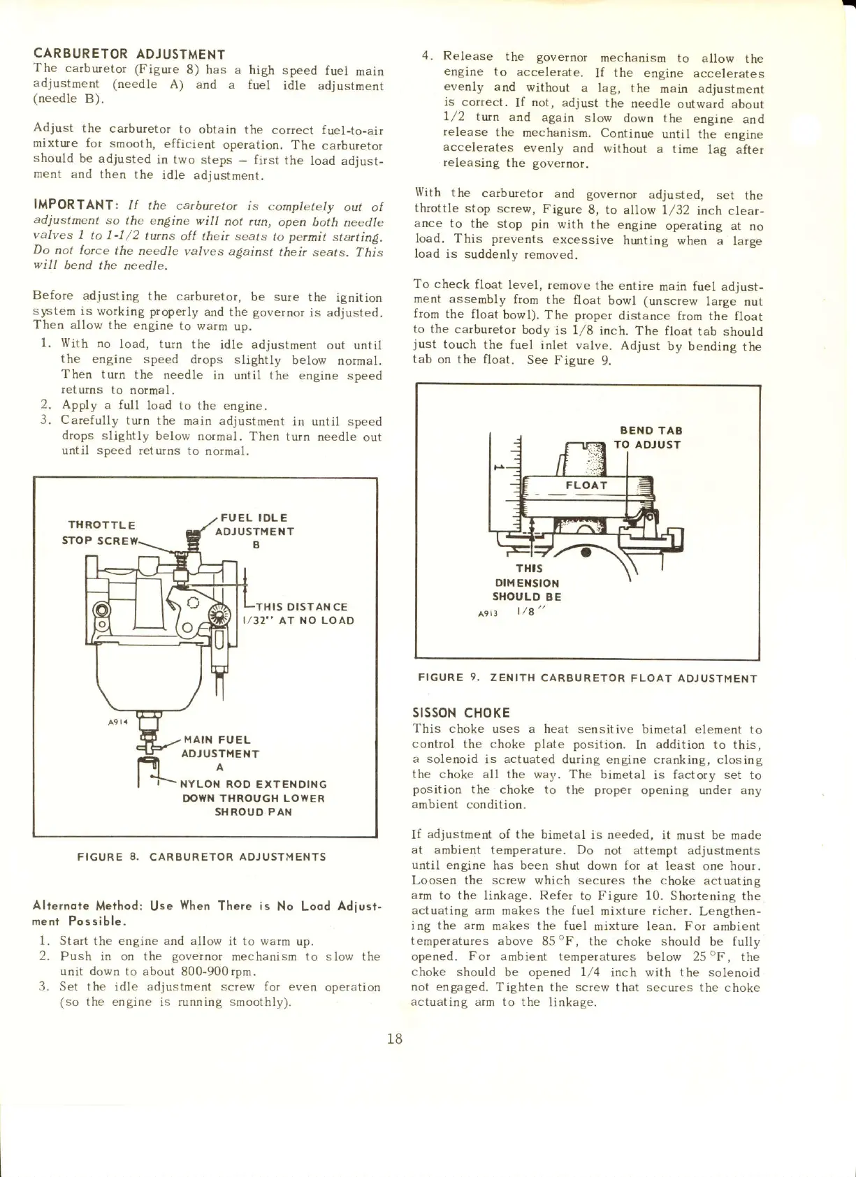
To check
float
level, femove
the
entire
main fuel
adjust-
ment
assembly
ftom
the
float bowl (unscrew
large nut
from
the float
bowl).
The
proper
distance
ftom the float
to
the carburetor
body
is
1/8
inch,
The float
tab should
just
touch
the fuel
inlet valve.
Adjust
by bending
the
tab
on the float.
See
Fieure
9.
SI{OULD
B E
A9rr
|/a"
FIGURE
9.
ZENITH
CARSURETOR
FLOAT
AOJUSTMENT
stssoN
cHoKE
This choke
uses a heat sensitive
bimetal element to
control
the
choke plate
position.
In
addition to this,
a solenoid
is actuated duting engine
cranking, closing
the
choke all the way. The
bimetal is factory set to
position
the choke to the proper
opening
under
any
ambient
condition,
If
adjustment
of the bimetal is needed,
it must be made
at ambient temperature. Do
oot
attempt adjustments
until
engine has been shut down for
at least
one
hour.
Loosen the
screw
which secures the choke
actuating
arm
to
the
linkage. Refer to Figure 10.
Shortening the
actuating
arm makes the fuel
mixture
richer.
Lengthen-
ing the arrn makes the fuel
mixture lean. For ambient
temperatufes above
85"F, the choke should
be fully
opened. For ambient temperatures
below 25"F, the
choke
should
be opened
l/4
inch with the solenoid
not engaged.
Tighten the screw that secures
the choke
actuating aim to
the linkage.
18
 Loading...


