I
ADJUSTTIENTS
GEN
ERAL
Satisfactory engine
performance
is largely dependent
upon corect adjustments.
However,
adjustments
can-
not fully compensate
for
low
engine
powet
due to wear,
etc.
If
ttouble
develops, follow an
orderly
procedure
to determine the cause
before
making
any adjustment.
Refer to the Troubleshooting
Chart for help in checking
causes of
troubles which
may occur,
BREAKER
POINTS
1. Remove the
two
screws and the cover
on
the
breaker box.
2. Remove the
two
spark
plugs
so
engine
can be
easily rotated by hand.
3. Turn
flywheel
in
a clockwise direction approxi-
mately
1/4 turn after top center (TC).
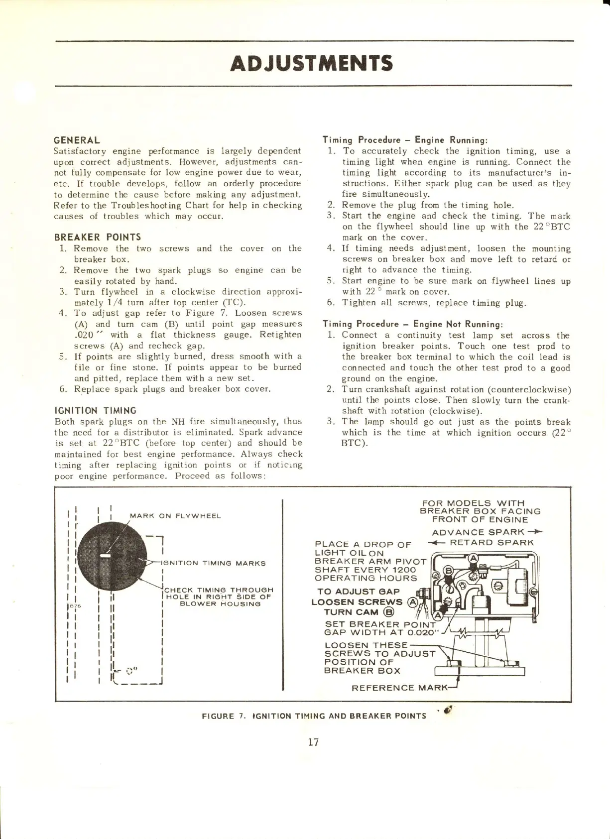
4. To adjust
gap refer to Figure 7,
Loosen
screws
(A)
and
turn
cam (B) until
point gap
measures
.020
"
with a flat thickness
gauge.
Retighten
screws
(A)
and
recheck
gap.
5.
If
points
are slightly
butned, dress smooth with a
file
or
fine stone.
If
points
appear to be
burned
and
pitted, replace them with a new set.
6.
Replace spark plugs and breaker box cover.
IGNITION TIMING
Both spark
plugs
on
the
NH
fire simultaneously, thus
the need for a distributor is
eliminated. Spark advance
is set
at 22oBTC (before top center) and
should be
maintained
for best engine performance. Always
check
timing after replacing
ignition
points
or if noticrog
poot
engine
performance.
Ptoceed
as follows:
Timing Procedure
-
Engine
Running:
1. To accurately
check the ignition timing, use a
tirning light when engine is running. Connect
the
timing light accotding to
its manufacturer's in-
structions.
Either spark
plug
calr
be used
as they
fite
simultaneously.
2. Remove the
plug
from
the timing hole.
3.
Start the engine and
check the timing. The
mark
on
the fllnvheel should
line up with the 22oBTC
mark on the cover.
4.
If
timing oeeds
adjustment,
loosen the
mourting
screws
on breaker box arrd
move left to retard
or
right
to
advance the timing.
5.
Start
engine
to be sure mark
on
fltmheel
lines up
wfth 22o mark on cover.
6.
Tighten all screws,
replace tirning
plug,
Timing Procedure
-
Engine
Not
Running:
1. Connect
a continuity test
lamp set acrcss the
ignition breaker points.
Touch one test
prod
to
the breaker box
terminal to which the coil
lead is
connected and touch the
other
test piod
to a
good
ground
or! the engine.
2. Turn crankshaft against rotation
(counterclockwise)
until the
points
close. Then slowly turn
the crank'
shaft with rotation (clockwise).
3. The
lamp
should go
out
just
as the points
break
which is the time at which
ignition
occurs
(22"
BTC).
I
I
t
I
MAFIK
ON FLYW HEEL
FOR
MODELS WITH
BREAKER
BOX FACING
FRONT
OF
ENGINE
ADVANCE SPARK
..>
OF
<- RETARD SPARK
--1
PLACE
A DROP
LIGHT
OILON
N TIMING
MARKS
BRE,AKER
ARM
PIVOT
SHAFT EVERY
,I2OO
OPERATING HOURS
ll
ll
tl
it
ii
il
..,,
rr:_'_
TO
ADJUST
OAP
LOOSEN
SCREWS
TURN
CAM
@
SET
BREAKER
GAP WIOTH AT
POI
o.o20"
LOOSEN THESE
SCREWS
TO ADJUST
_)
POSITION
OF
BREAKER
BOX
REFERENCE
MARK
FIGURE
7.
IGNITION TIMING
AND
BREAKER
POINTS
.
d
T7
 Loading...


