!
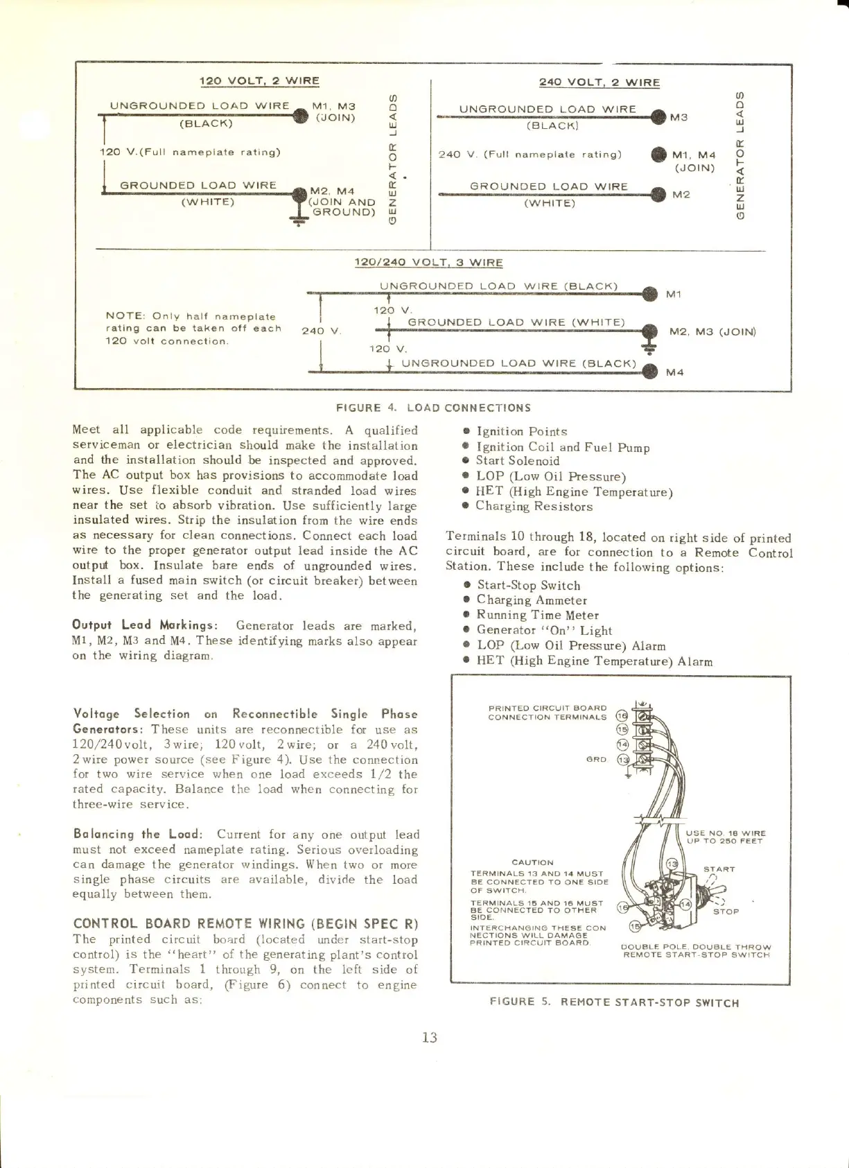
120 VOLT, 2 W|RE
UNGROUNDED LOAD
WIRE
^
M1, M3
T,"-"',
I
(BLACK)
I
120
V.(Full
nameplate rating)
240 VOLT,
2 W|RE
UNGROUNDED
LOAD
\^/IRE
+M3
(BLACK]
a
o
IJJ
)
c
ul
z
uJ
o
U'
o
J
E.
f-
E.
ul
z
o
240
V. nameplare rating)
|
r,ar. r,,ll
(JOIN)
GROUNDED
LOAD
(w
H rTE)
M'2.
M4
(JOIN
AND
6ROUND)
GROUNDEp LOAp
W|RE
I
M2
(wHtTE)
NOTE:
On
ly
halt nameplat€
rating can be taken
oft each
120 volt
connsction.
'r20l240
voLT.
3 WtRE
UNGROUNDED
LOAD WIRE
(ALACK)
FIGURE
4.
LOAD
CONN
ECTION S
M2,
M3
(JO|N)
120
V.
Meet all applicable code
requirements.
A
qualified
serviceman
or
electlician should
oake the installation
and
the installation should
e inspected and
approved.
The
AC
output box
has
provisions
to accommodate
load
wires.
Use
flexible
conduit and stranded
load wires
near the set
io absorb vibtation.
Use
sufficiently
large
insulated u'ires. Strip
the insulation from
the wire ends
as
necessary for
clean connections.
Connect each
load
u'ire to the
proper
geneEtor
output lead inside
the
AC
outpd box.
Insulate bare
ends
of
ungrounded wires.
Install
a fused
main switch (or
circuit breaker)
between
the
generating
set and
the load.
Output Leod Morkings:
Generator leads
are marked,
M1, M2, M3
and
Mq.
These
identifying marks also appear
on
the wiring diagram.
Yoltoge Selection on Reconnectible Single
Phose
Generqlors: These units are reconnectible for
use
as
120/240volt,
3wire; 120volt, 2wire;
or
a 240volt,
2wire
power source (see
Figure 4).
Use
the connection
for two wire service vrhen
one load exceeds 1/2 the
rated capacity. Balance the load when condectiflg
for
three-wire
service.
Boloncing
the Lood: Current for
any one output lead
ftust not exceed
nameplate
rating.
Serious
overloading
can
damage the
generator
windings.
When two
ot
more
single phase
circuits are available, divide
the load
equally between them.
CONTROL
BOARD REMOTE
WIRING
(BEGIN
SPEC R)
The
printed
circuit
board (located
uder
start-stop
control)
is the
"heart"
of the
generating
plart's control
system. Terminals 1
through 9, on the left side
of
printed circuit
board,
@igure
6)
connect
to
engine
components such
as:
.
Ignition
Points
a
Ignitioq Coil
and Fuel
Purnp
a
Start Solenoid
.
LOP
(Low
Oil Pressure)
.
HET
(HiCh
Engine
Temperatule)
r
Charging
Resistors
Terminals
10
through 18,
located
on right side
of
printed
citcuit
boatd,
aie
for
connection
to a Remote Control
Station.
These
include
the following
options:
.
Stalt-Stop
Switch
a
Charging
Arnrneter
a
Running
Time
Meter
a
Generator
,,On',
Light
a
LOP (Low
Oil
Pressure) Alarrn
.
HET
(HiCh Engine
Ternperature)
Alarm
PRINTEO CIRCUIT
AOARO
CONNECTION
TERMINAIS
@
@
o
TERMINALS
13 ANO 14 MUSA
EE CONNECTEO TO
ONE SIDE
TERMINALS 15 ANO 16 MUST
BE
CONNECTED TO
OTHER
INTEFICHAN6ING
THESE CON
N€CTIONS WILL OAMAGE
PRINIED C'RCUIT BOARD
,a'
OOUBLE
PO!E
OOUBLE THROv/
REMOTE
START.STOP SWITCH
UNGROUNDED LOAD WIRE
(B
LACK)
13
FIGURE
5.
REMOTE
START.STOP
SWITCH
 Loading...


