Connection
−14−
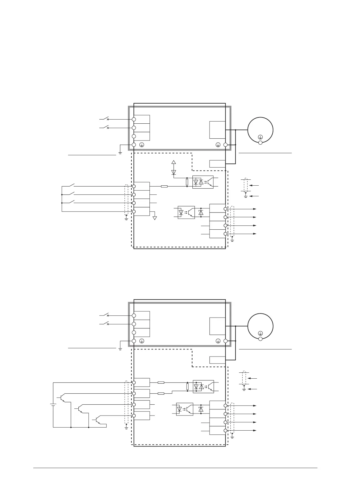
5.5 Connection diagram
The connection example is of the single-phase input. The power supply connection for the three-phase input is different.
(5.3 Connecting the power supply
⇒
p.12)
Sink logic
z
When using the built-in power supply
This is a connection example for when the built-in power supply is used for input signals.
The I/O signal in the brackets [ ] is the assignment at the time of shipment.
Grounding the driver
Be sure to ground.
Grounding the motor ∗
Be sure to ground.
Motor connection
L
Motor connector
CN1
CN2
N
NC
Motor
Main circuit
Control circuit
CN4
7
6
5
C1䠄0 V䠅
8
0 V
Power supply
connection
L
N
Circuit breaker
Shielded cable
Grounding
680 Ω
820 Ω
X1䠷REV䠹
X0䠷FWD䠹
+5 V
X2䠷M0䠹
Sensor
connector
CN3
4
3
2
1
䠷SPEED-OUT䠹
䠷ALARM-OUT1䠹
Y0+
Y0−
Y1+
Y1−
*
Be sure to ground. Refer to "5.2 Grounding" on p.11 for grounding.
z
When using the external power supply
This is a connection example for when the external power supply is used for input signals.
The I/O signal in the brackets [ ] is the assignment at the time of shipment.
Connecting input signals
20.4䡚28.8 VDC
100 mA or more
CN4
7
6
9
8
Shielded cable
Grounding
5 kΩ
680 Ω
820 Ω
X1䠷REV䠹
X0䠷FWD䠹
C0
X2䠷M0䠹
Motor conanection
L
Motor coannector
CN1
CN2
N
NC
Motor
Main circuit
Control circuit
Power supply
connection
L
N
Circuit breaker
Sensor
connector
CN3
4
3
2
1
Y0+
Y0−
Y1+
Y1−
䠷SPEED-OUT䠹
䠷ALARM-OUT1䠹
Grounding the motor ∗
Be sure to ground.
Grounding the driver
Be sure to ground.
*
Be sure to ground. Refer to "5.2 Grounding" on p.11 for grounding.
Refer to the p.16 for
connection of output signals.
Refer to the p.16 for
connection of output signals.
 Loading...