Preparation
−7−
3.3 Products possible to combine
Products with which drivers can be combined are listed below.
Verify the driver model and the motor model against the model name described on the package label.
For details about the motor, refer to the operating manual supplied with the motor.
Output power Power supply voltage Driver model Motor model
*
30 W
Single-phase 100-120 V
BMUD30-A2
BLM230-
oo
,
BLM230HP-
oo
Single-phase, Three-phase 200-240 V
BMUD30-C2
60 W
Single-phase 100-120 V
BMUD60-A2
BLM260-
oo
,
BLM260HP-
oo
BLM460S-
oo
,
BLM460SHP-
oo
BLM460SHPK-
oooo
Single-phase, Three-phase 200-240 V
BMUD60-C2
120 W
Single-phase 100-120 V
BMUD120-A2
BLM5120-
oo
,
BLM5120HP-
oo
BLM5120HPK-
oooo
Single-phase, Three-phase 200-240 V
BMUD120-C2
*
o
in the motor model name indicates a code or a number representing the gear ratio, the shaft shape, or the gearhead type.
3.4 Names and functions of parts
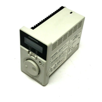
Front side
When the front panel is attached
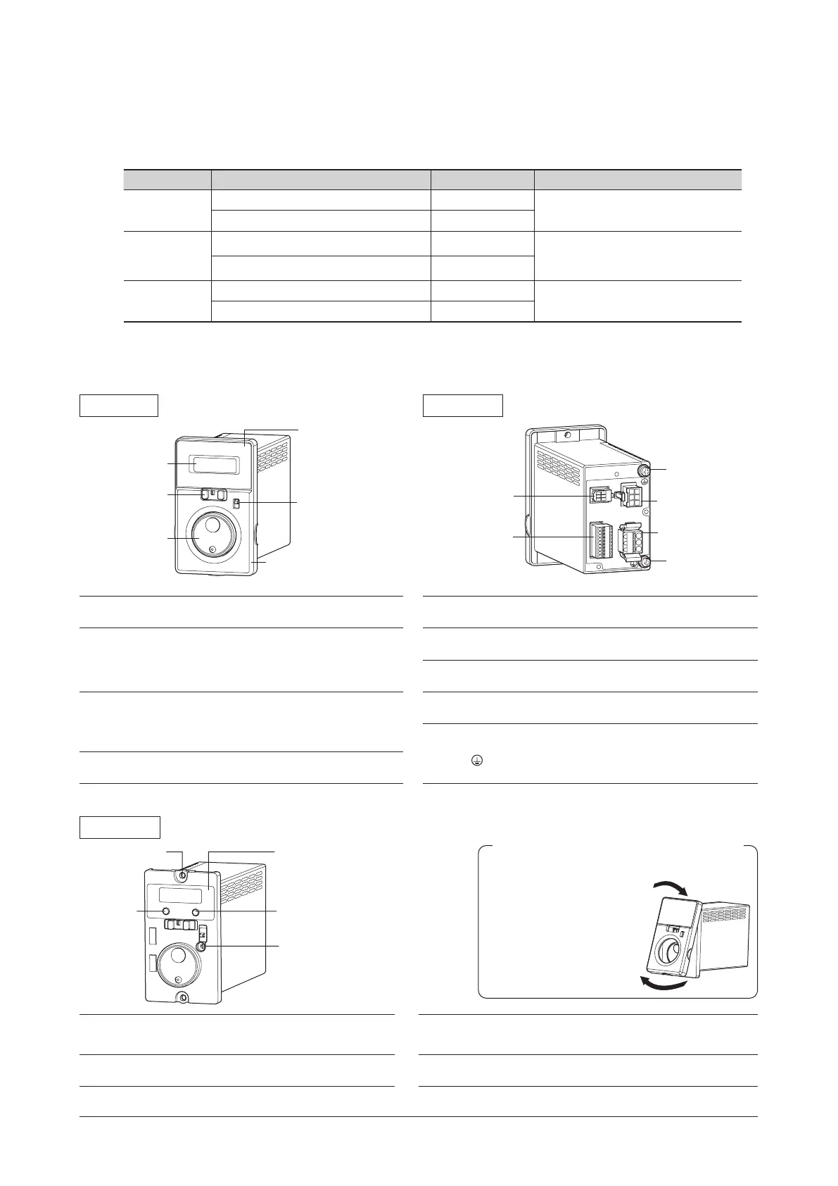
Rear side
Display
Operation switch
Setting dial
Front panel
Rotation direction
switch
Use after removing
the protective lm.
I/O signals
connector
(CN4㻕
Protective
Earth Terminal
Protective
Earth Terminal
Sensor connector
(CN3)
Motor connector
(CN2)
Main power supply
connector (CN1)
Display
This display shows the monitor item, alarms,
etc.
Sensor connector
(CN3)
Connects the sensor connector (black) of the
motor cable or the connection cable.
Operation switch
Setting the operation switch to the "RUN" side
causes the motor to start running.
Setting the operation switch to the "STAND-BY"
side causes the motor to stop.
I/O signals connector
(CN4)
Connects the I/O signals.
Motor connector
(CN2)
Connects the power connector (white) of the
motor cable or the connection cable.
Setting dial
This setting dial is used to change the rotation
speed or parameters.
After changing, the new value is determined
by pressing the setting dial.
Main power supply
connector (CN1)
Connects the main power supply.
Protective Earth
Terminal
Connects the ground terminal
*
of the
connection cable and the grounding wire.
Be sure to ground the driver using either of
the Protective Earth Terminals.
Rotation direction
switch
This switch is used to change the motor
rotation direction.
*
Connector type only
Front side
When the front panel is removed
FUNCTION key
(2 locations)
MODE key
Acc
time potentiometer
Use after removing
the protective lm.
MODE key
This key is used to change the operation
mode.
Acceleration/deceleration
time potentiometer
This potentiometer is used to set the
acceleration/deceleration time.
FUNCTION key
This key is used to change the display of
the operation mode or the function.
Mounting hole
(2 locations)
Installs the driver with screws
(M4 or No.8-32UNC).
Removing
Remove the front panel
having the under side.
Installing
Install the front panel after
placing on the upper side of
the driver front face.
Removing and installing the front panel
 Loading...