12
WIRE CONNECTIONS
NOTE: A system’s individual voltage requirements (230 or 3-phase) as well as how each FX is to
function all determine how the FXs are wired. Each FX must be wired to the logical leg or phase of the
system. Each FX must be programmed or “stacked” according to this phase. Please see the International
FX and VFX Series Inverter/Charger Programming Manual before connecting any wires to or from the FX.
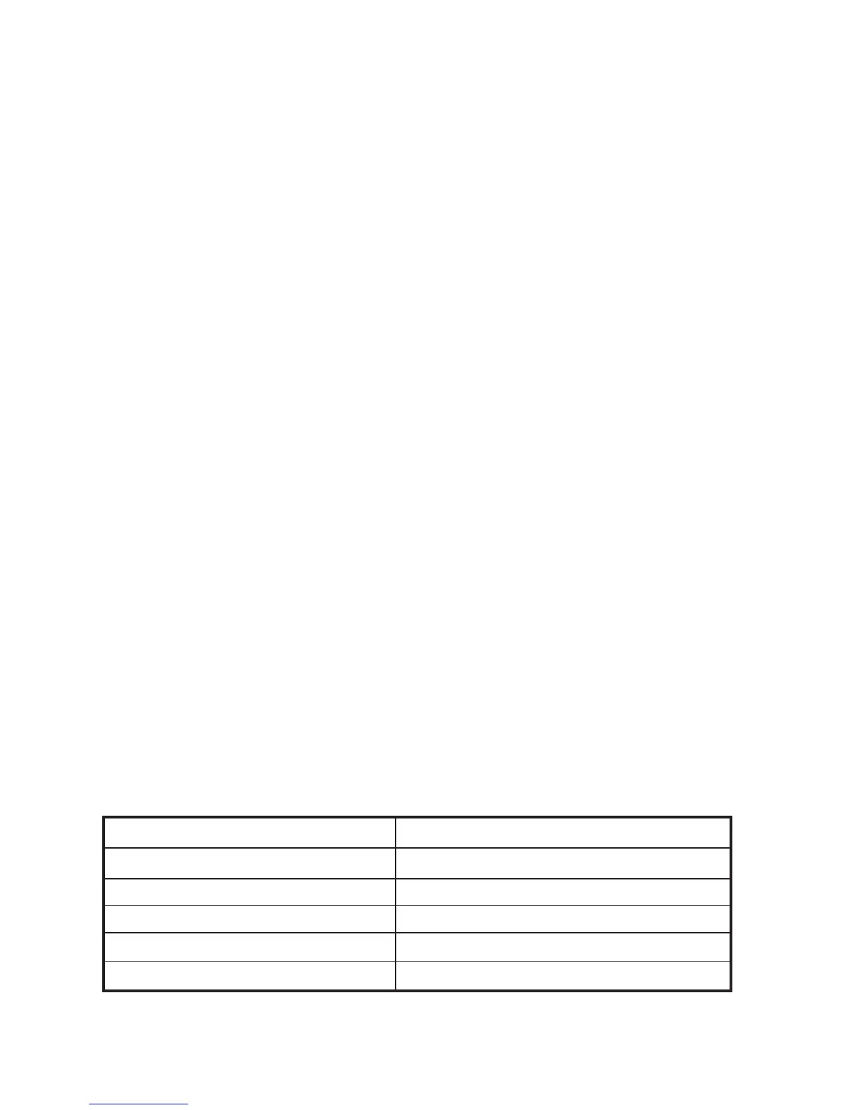
TORQUE REQUIREMENTS
CONNECTION TORQUE IN POUND MEASURES
AC and PV breakers to 22 inch-lbs = 2.5 Nm
DC shunt to 15 foot-lbs = 20.4 Nm
DC battery connections to 10 foot-lbs = 13.6 Nm
FX’s DC Terminals to 10 foot-lbs = 13.6 Nm
FX’s AC Terminals to 30 inch-lbs = 3.38 Nm
Table 1 Torque Values for Installation
AC
Follow these steps to wire the FX to your system:
1. Shut all AC breakers o or remove any fuses before connecting any wiring.
2. Shut o all DC breakers, including the PV breakers.
3. With all power o , run lengths of 6 AWG (16.0 mm
2
)
wire between the AC Wiring Compartment
Board AC out terminals and su cient over current protection via an AC circuit breaker whose
ampacity matches or exceeds the maximum AC input current of the FX model used in the system
(see FX product speci cations). The breaker should be installed inside of a metal chassis such as
OutBack’s FLEXware series or an existing panel.
4. With the over current protection connected, run lengths of 6 AWG (13.3 mm
2
) wire between the
AC Wiring Compartment Board AC IN terminals and the AC input breaker. The breaker should be
installed inside of a metal chassis such as OutBack’s FLEXware series or an existing panel. The AC
input hot conductor must be supplied through an AC branch-rated circuit breaker whose ampacity
matches or exceeds the maximum AC input current of the FX model used in the system (see FX
product speci cations)
DC
• Use crimped and sealed copper ring terminal lugs with 5/16” (8 mm) hole or compression-type lug to
connect battery cables to DC terminals. Soldered cable lugs are also acceptable.
• Use recommended cable sizes (see page 36) to reduce losses and ensure high performance of FX (smaller
cables can reduce performance and possibly damage the unit).
• Keep cables together (e.g., using a tie-wrap) as much as possible.
• Ensure cables pass through the same knockout and conduit ttings to allow inductive currents to cancel.
 Loading...