66
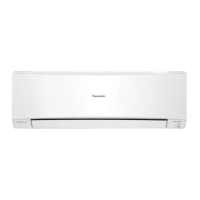
11.3.3 Evacuation of the Equipment
WHEN INSTALLING AN AIR CONDITIONER, BE SURE TO EVACUATE THE AIR INSIDE THE INDOOR UNIT AND
PIPES in the following procedure.
1 Connect a charging hose with a push pin to the Low side of a charging set and the service port of the 3-way
valve.
o Be sure to connect the end of the charging hose with the push pin to the service port.
2 Connect the center hose of the charging set to a vacuum pump.
3 Turn on the power switch of the vacuum pump and make sure that the needle in the gauge moves from
0 cmHg (0 MPa) to -76 cmHg (-0.1 MPa). Then evacuate the air approximately ten minutes.
4 Close the Low side valve of the charging set and turn off the vacuum pump. Make sure that the needle in the
gauge does not move after approximately five minutes.
Note: BE SURE TO TAKE THIS PROCEDURE IN ORDER TO AVOID REFRIGERENT GAS LEAKAGE.
5 Disconnect the charging hose from the vacuum pump and from the service port of the 3-way valve.
6 Tighten the service port caps of the 3-way valve at a torque of 18 N•m with a torque wrench.
7 Remove the valve caps of both of the 2-way valve and 3-way valve. Position both of the valves to “OPEN”
using a hexagonal wrench (4 mm).
8 Mount valve caps onto the 2-way valve and the 3-way valve.
o Be sure to check for gas leakage.
If gauge needle does not move from 0 cmHg (0 MPa) to -76 cmHg (-0.1 MPa), in the step e above take the following measure:
- If the leak stops when the piping connections are tightened further, continue working from step e.
- If the leak does not stop when the connections are retightened, repair location of leak.
- Do not release refrigerant during piping work for installation and reinstallation.
- Take care of the liquid refrigerant, it may cause frostbite.
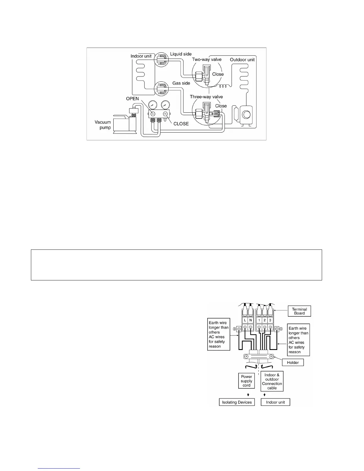
11.3.4 Connect the cable to the Outdoor Unit
1 Remove the control board cover from the unit
by loosening the screw.
2 Cable connection to the power supply through
Isolating Devices (Disconnecting means).
o Connect approved type polychloroprene
sheathed power supply cord 3 x
1.5 mm
2
(3/4 ~ 1.75HP), 3 x 2.5 mm
2
(2.0 ~ 2.5HP) or 3 x 4.0 mm
2
(3.0HP)
type designation 245 IEC 57 or heavier
cord to the terminal board, and connect
the others end of the cord to Isolating
Devices (Disconnecting means).
3 Connection cable between indoor unit and
outdoor unit shall be approved
polychloroprene sheathed 4 x 1.5 mm
2
flexible
cord, type designation 245 IEC 57 or heavier
cord.
4 Connect the power supply cord and
connection cable between indoor unit and
outdoor unit according to the diagram below.
 Loading...