33
7.2. Checking Method of Drive Circuit
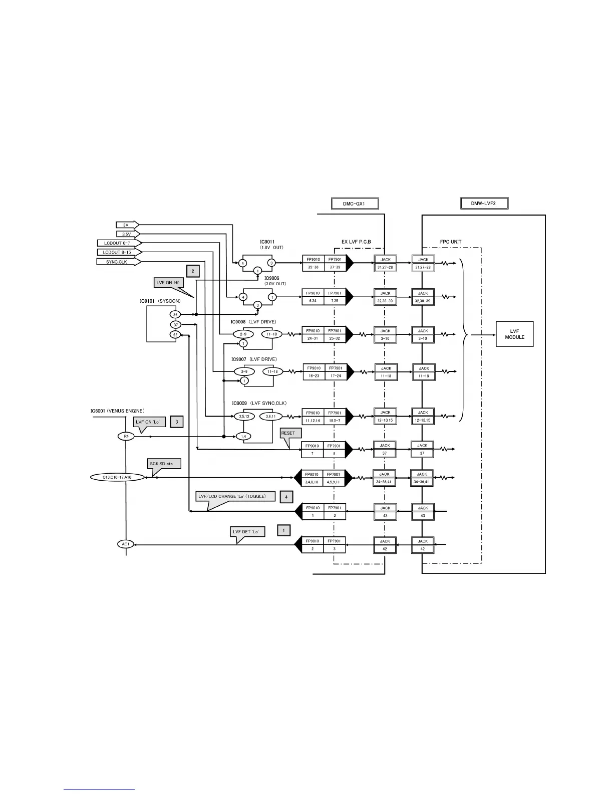
• It is a circuit operation and a check method when optional external live viewfinder (DMW-LVF2) is attached.
[Circuit Operation]
• When DMW-LVF2 is attached, DMC-GX1 supplies the power source and various signals to DMW-LVF2.
1. When DMW-LVF2 is attached, Pin 2 of FP9010 becomes 'Lo' (GND), then IC6001 (VENUS ENGINE) detects the installation.
-------- [1]
2. Pin 86 of IC9101 (SYSCON) becomes 'Hi' at DMW-LVF2 display mode, 1.8V is outputted from pin 3 of IC9011 and 3V is out-
putted from pin 1 of IC9006. -------- [2]
3. Pin R4 of IC6001 becomes 'Lo', and various signals are output from IC9007 - IC9009 to DMW-LVF2. -------- [3]
4. The display changes whenever the [LVF/LCD] switch button of DMW-LVF2 is pressed. -------- [4]
* As for the switch with the [LVF/LCD] button, the power supply of DMC-GX1 of turning off is maintained.

 Loading...