41
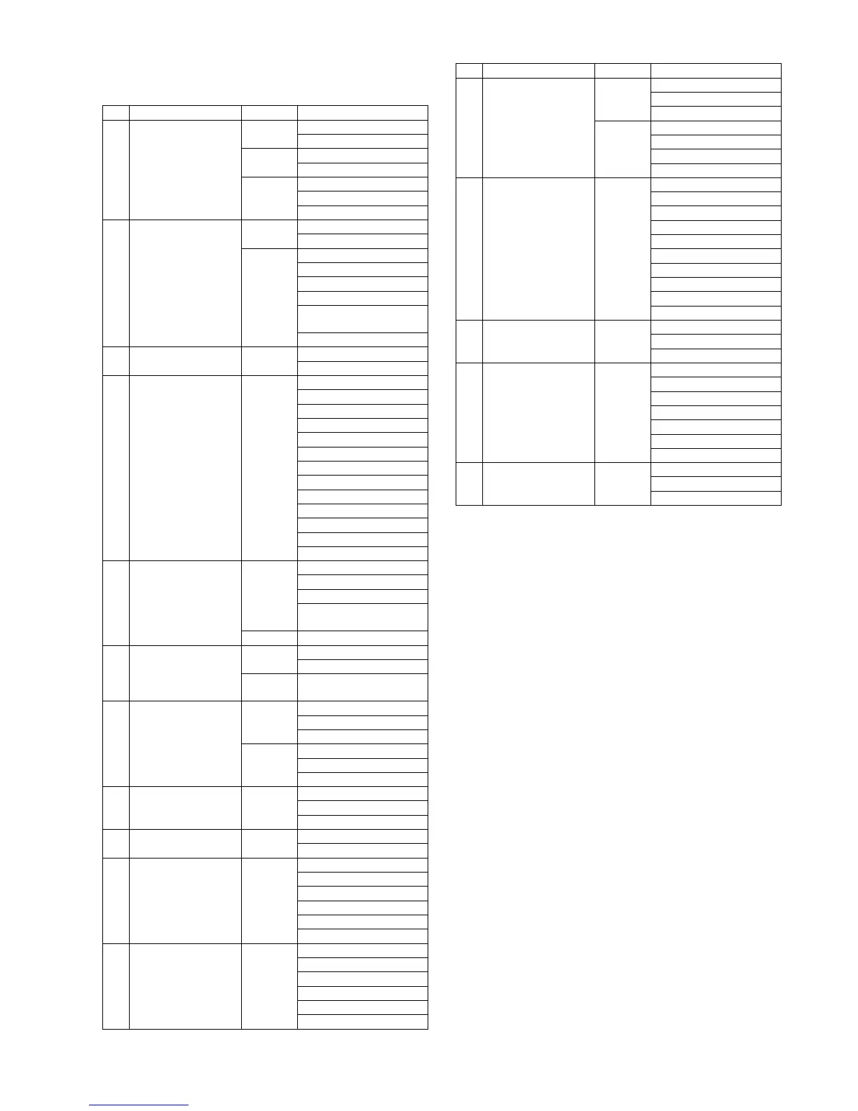
9.1.3. Disassembly Procedure
No. Item Fig Removal
1 Rear Case Unit (Fig. D1) Shoe Cover
Shoe Spring
(Fig. D2) 2 Screws (A)
6 Screws (B)
(Fig. D3) FP9003 (Flex)
FP9007 (Flex)
Rear Case Unit
2 LCD Unit (Fig. D4) 1 Screw (C)
Grip Piece Rear
(Fig. D5) 1 Screw (D)
2 LCD FPC Tapes B
2 Locking tabs (A)
2 Locking tabs (B)
Rear Operation FPC &
Rear LCD Plate
LCD Unit
3 Rear Operation FPC (Fig. D6) Rear LCD Plate
Rear Operation FPC
4 Main P.C.B. (Fig. D7) FP9010 (Flex)
FP3911 (Flex)
FP3912 (Flex)
FP3913 (Flex)
FP9001 (Flex)
FP9002 (Flex)
FP9004 (Flex)
FP9005 (Flex)
FP9006 (Flex)
3 Screws (E)
1 Hooking part
P9001 (Connector)
Main P.C.B.
5 Front Case Unit &
Mount Box Unit
(Fig. D8) 5 Screws (F)
1 Screw (G)
2 Screws (H)
Front Case Unit &
Mount Box Unit
(Fig. D9) Note: (When Installing)
6 Mount Box Unit (Fig. D10) 3 Screws (I)
Mount Box Unit
(Fig. D11) Handling Precautions of
Mount Box Unit
7 Capacitor P.C.B. Unit (Fig. D12) 1 Screw (J)
1 Screw (K)
Tripod Fixing Plate
(Fig. D13) Capacitor Tape
1 Locking tab
Capacitor P.C.B. Unit
8 Top Unit (Fig. D14) 1 Screw (L)
1 Locking tab
Top Unit
9 EX LVF P.C.B. (Fig. D15) 2 Screws (M)
EX LVF P.C.B.
10 Flash Lock Unit
Top Case Unit
(Fig. D16) 1 Screw (N)
Shoe Plate
2 Screws (O)
3 Convex portions
Flash Lock Unit
Top Case Unit
11 Mic Unit (Fig. D17) FP8005 (Flex)
2 Ribs
Mic Cushion (C)
Mic Unit
Mic Cushion (B)
Mic Cushion (A)
12 Top P.C.B. (Fig. D18) 2 Screws (P)
FP8004 (Flex)
Rear Dial Switch Unit
(Fig. D19) 1 Screw (Q)
FP8002 (Flex)
FP8003 (Flex)
Top P.C.B.
13 Speaker
Flash P.C.B.
(Fig. D20) 1 Screw (R)
1 Screw (S)
Speaker
1 Screw (T)
Side Plate (R)
Strap Holder
1 Screw (U)
2 Solders
P8502 (Connector)
Flash P.C.B.
14 Battery Door Unit (Fig. D21) Battery Door Shaft
Battery Door Spring
Battery Door Unit
15 Battery Case (Fig. D22) 2 Locking tabs
Jack Door
4 Locking tabs
Battery Case
Battery Out Spring
Battery Lock Knob
Battery Lock Spring
16 Heat Radiation Plate (Fig. D23) 1 Locking tab
2 Convex portions
Heat Radiation Plate
No. Item Fig Removal
 Loading...