EasyManuals Logo
Home>Parker>Engine>GVM Series

Parker GVM Series User Manual

Parker GVM Series
82 pages
To Next Page IconTo Next Page
To Previous Page IconTo Previous Page
Page #18 background imageLoading...
Page #18 background image
- 18
18-06-08 PVD3668_GB_GVM_June_2018
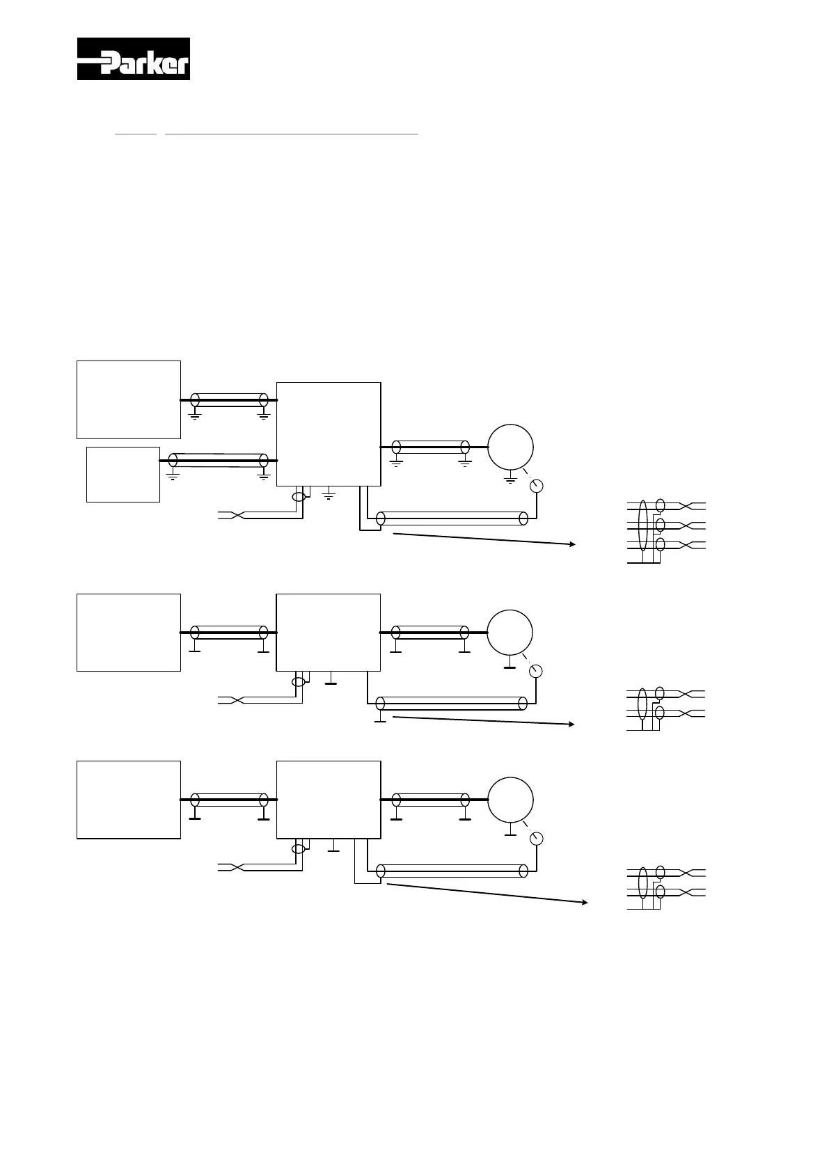
3.2.1. Motor Drive Connection Rules
Each Drive has its own connection rules, typically about shielding connection.
Please find hereafter the recommended connection rules for MC and MD drives we can provide associated
with GVM motors (see page 20, 22, 24 & 25).
For best noise immunity, all power cables (motor / battery) should not run across the centre section of the
controller.
Low current signal wires should not run parallel to the motor cables. When necessary, they should cross the
motor cables at right angle to minimize noise coupling.
Following instructions are given as general rules to respect for standard architecture, all other connections like
I/O, throttles … must respect rules as well. Some adjustments could be necessary.
All connections, settings, architectures are not under PARKER responsibility
GVM
DRIVE
MD-4A
MD-4B
MD-4C
POWER BATTERY
High Voltage
Resolver
Excit +
Excit -
Sin +
Sin -
Cos +
Cos -
Encoder 0V
CAN H
CAN L
CAN GND
CONTROL
BATTERY
Low Voltage
GVM
DRIVE
MD-42
MD-44
MD-46
BATTERY
Sincos
Enco der
+5V su pply
0V
Sin
Cos
B-
CAN H
CAN L
B-
B-
B- B- B-
B-
B-
B-
GVM
DRIVE
MC
BATTERY
B-
B- B- B-
B-
B-
I/O GND (Pin 7)
+5V su pply
0V
Sin
Cos
I/O GND (pin 7)
Sincos
Enco der
CAN H
CAN L
I/O GND (Pin 7)

Table of Contents

Questions and Answers:

Question and Answer IconNeed help?

Do you have a question about the Parker GVM Series and is the answer not in the manual?

Parker GVM Series Specifications

General IconGeneral
BrandParker
ModelGVM Series
CategoryEngine
LanguageEnglish

Related product manuals